Wheel Speed Sensor: Complete Guide
Wheel Speed Sensor: What It Does, Why It Fails, and How to Diagnose It
The wheel speed sensor is a small electromagnetic or Hall-effect transducer mounted at each wheel hub that measures how fast that individual wheel is rotating. It is the primary data source for the anti-lock braking system (ABS), traction control, and electronic stability control — the three safety systems that prevent wheel lockup, wheelspin, and skidding. Without accurate wheel speed data, these systems cannot function, and in many modern vehicles the engine management, transmission shift logic, and tire pressure monitoring also depend on the same signal. This makes the wheel speed sensor one of the most safety-critical, yet most commonly overlooked, components in a car.
In this guide, we cover the sensor’s full anatomy: how it generates a signal, the difference between magnetic and active digital types, typical failure modes (worn bearings, damaged wiring, corroded connectors), and the exact diagnostic steps — including how to read the live data with an OBD-II scanner and interpret the voltage waveform on an oscilloscope. We also look at real-world replacement costs, OEM versus aftermarket quality differences, and the most common misdiagnoses that lead to unnecessary part replacements. If you are troubleshooting an ABS warning light, a traction control malfunction, or a speedometer that reads zero, this article gives you the decision framework to pinpoint the failing sensor quickly and confidently.
What Is a Wheel Speed Sensor and How Does It Work?
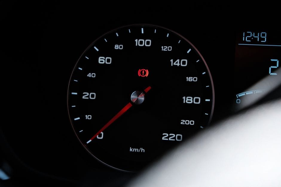
A wheel speed sensor is a small electronic device mounted at each wheel that measures how fast that wheel is rotating. It sends that data continuously to the vehicle’s ABS control module, which uses the information to manage anti-lock braking, traction control, and stability control. Without these sensors, your car would still drive, but its most important safety systems would be blind.
The role of the wheel speed sensor in your vehicle’s safety systems
Every modern car has four wheel speed sensors — one at each corner. The ABS control module compares the rotational speed of all four wheels dozens of times per second. When you brake hard and one wheel locks up, that wheel’s speed drops faster than the others. The module detects this difference and pulses the brake pressure to that wheel, preventing a skid.
The same data feeds traction control (when a drive wheel spins faster than the others) and electronic stability control (when the car’s actual direction doesn’t match the steering input). A single fa
Active vs. passive sensors: key differences
There are two main types of wheel speed sensors: passive (also called variable reluctance or magnetic) and active (Hall effect or magnetoresistive). Passive sensors generate their own AC voltage signal as the tone ring passes by a magnetic coil — they require no external power and produce a sine wave whose frequency increases with wheel speed. However, they become unreliable at very low speeds (below about 3–5 mph), which limits their usefulness for modern stability control systems.
Active sensors, by contrast, use a Hall effect or magnetoresistive element and require a regulated power supply from the ABS module. They produce a clean digital square-wave signal that works down to zero speed, making them the standard on all vehicles built after roughly 2000. Active sensors are also more accurate and can detect the direction of rotation in some implementations, which is essential for hill-hold and roll-back prevention features.
How the sensor communicates with the ABS/ESC module
The sensor sends its signal through a twisted-pair wiring harness directly to the ABS control module. The module interprets the frequency and pattern of the signal to calculate wheel speed, acceleration, and deceleration. In active sensor systems, the module also supplies a reference voltage (typically 5V or 12V) to the sensor. The communication is continuous and real-time — the module samples each wheel’s speed dozens of times per second to make split-second braking decisions. If the signal is interrupted, corrupted, or out of expected range, the module sets a diagnostic trouble code (DTC) and illuminates the ABS warning light.
Where Is the Wheel Speed Sensor Located and How to Access It
Front vs. rear sensor placement differences
Front wheel speed sensors are typically mounted through the steering knuckle or spindle, with the sensor tip positioned just a millimeter or two from the tone ring on the CV joint or hub assembly. Rear sensors are usually mounted on the backing plate of the drum brake or the hub carrier of the disc brake. On many vehicles, the front sensors are more exposed to road debris, salt, and water, making them more prone to corrosion and wiring damage. Rear sensors are often more protected but can be harder to reach due to limited clearance.
Tools needed for access
Accessing a wheel speed sensor typically requires a basic socket set, a Torx or hex bit set (many sensors use T30 or 8mm bolts), a trim removal tool for plastic covers, and possibly a breaker bar for seized bolts. You’ll also need a jack and jack stands to safely lift the vehicle. For sensors mounted inside the hub, a slide hammer or bearing puller may be necessary. A digital multimeter or oscilloscope is essential for electrical testing.
Visual inspection points
Before removing anything, inspect the sensor wiring harness for cuts, chafing, or melted insulation — especially near the suspension components and tires. Check the connector for corrosion, bent pins, or moisture ingress. Look at the tone ring through the sensor mounting hole: it should be clean, free of cracks, missing teeth, or excessive rust buildup. Also check the wheel bearing for play, as excessive bearing wear can cause the tone ring to contact the sensor tip, damaging both components.
Common Symptoms of a Failing Wheel Speed Sensor

ABS warning light illumination
The most obvious symptom is the ABS warning light on the dashboard. When the ABS module detects an implausible or missing signal from one or more wheel speed sensors, it illuminates the ABS light and disables the anti-lock braking system. In many vehicles, the traction control and stability control lights will also illuminate simultaneously, as they rely on the same sensor data.
Traction control and stability control malfunctions
A failing sensor can cause the traction control system to activate unexpectedly — you might feel the brakes pulse or the engine power cut when driving on dry pavement. Similarly, the stability control system may intervene incorrectly, causing the car to feel like it’s “fighting” your steering inputs. These symptoms often appear before the ABS light comes on, as the module may still receive a signal but one that is erratic or out of range.
Speedometer and odometer inaccuracies
On many vehicles, the speedometer signal is derived from the wheel speed sensors (especially on cars without a separate transmission-mounted vehicle speed sensor). A failing wheel speed sensor can cause the speedometer to read zero, fluctuate wildly, or show an incorrect speed. The odometer may also stop accumulating miles, and in some cases the transmission may shift erratically because it relies on the same speed data.
ABS activation at low speeds
If the sensor produces a weak or intermittent signal, the ABS module may interpret this as a wheel locking up and activate the ABS pump unnecessarily. You might feel a pulsing brake pedal at low speeds, especially when coming to a stop. This is both annoying and potentially dangerous, as it can increase stopping distances.
Why Wheel Speed Sensors Fail

Wiring and connector corrosion
The most common cause of wheel speed sensor failure is corrosion or damage to the wiring and connector. The sensors are located in the wheel well, where they are exposed to water, road salt, mud, and temperature extremes. Over time, moisture can enter the connector and corrode the pins, or the insulation on the wiring can crack and allow water to short the circuit. This is especially common in regions that use road salt in winter.
Damaged tone ring or reluctor ring
The tone ring — a toothed metal ring that the sensor reads — can become damaged due to rust, cracks, or missing teeth. On some vehicles, the tone ring is pressed onto the CV joint
or hub assembly and can be damaged during improper bearing replacement or by impact from road debris. A damaged tone ring produces an erratic or weak signal, even if the sensor itself is perfectly functional. Rust buildup between the teeth is a particular problem in colder climates, as it can effectively “fill in” the gaps and cause the sensor to lose its signal entirely.
Wheel bearing wear and sensor gap issues
Excessive play in the wheel bearing can cause the tone ring to move away from or into the sensor tip, changing the air gap. Most sensors require a gap of 0.2 to 1.5 millimeters to function correctly. If the bearing wears and allows lateral movement, the gap may become too large for the sensor to detect the tone ring, or the ring may physically contact and damage the sensor tip. This is why a failing wheel bearing is often misdiagnosed as a bad wheel speed sensor.
Sensor tip contamination and physical damage
The sensor tip can become coated with metallic debris, brake dust, or magnetic particles that interfere with its ability to detect the tone ring. Physical damage from road debris, improper installation, or contact with the tone ring can also crack the sensor housing or break the internal components. In some cases, the sensor’s internal electronics simply fail due to age, heat, or manufacturing defects.
How to Diagnose a Faulty Wheel Speed Sensor

Using an OBD-II scanner to read trouble codes
The first step in diagnosing a wheel speed sensor issue is to connect an OBD-II scanner and read the diagnostic trouble codes. Common codes include C0035 (left front sensor circuit), C0040 (right front), C0045 (left rear), and C0050 (right rear), along with codes like C0036, C0041, C0046, and C0051 for circuit range/performance issues. The specific code will tell you which sensor is affected and whether the problem is an open circuit, short, or signal plausibility issue. Write down all codes, including pending codes, before clearing them.
Reading live data from each wheel sensor
Using the OBD-II scanner’s live data mode, you can view the speed reading from each wheel sensor in real time. With the vehicle on jack stands, spin each wheel by hand and compare the readings. All four should show similar values and respond immediately to wheel rotation. A sensor that reads zero, shows erratic values, or fails to respond is likely faulty. You can also drive the vehicle slowly while monitoring live data — a sensor that drops out or spikes during driving has an intermittent connection issue.
Testing sensor resistance and voltage output
For passive sensors, disconnect the sensor connector and measure the resistance across the two pins using a digital multimeter. Typical resistance values range from 500 to 2,000 ohms, depending on the vehicle. An open circuit (infinite resistance) or a short (near-zero resistance) indicates a failed sensor. For active sensors, check that the supply voltage is present (typically 5V or 12V) and that the ground is intact. You can also measure the sensor’s output voltage while spinning the wheel — a passive sensor should produce an AC voltage that increases with speed, while an active sensor should produce a digital square wave.
Using an oscilloscope to check the signal waveform
An oscilloscope provides the most definitive diagnosis. Connect the scope leads to the sensor output and ground, then spin the wheel. A healthy passive sensor produces a clean, uniform sine wave whose amplitude and frequency increase with wheel speed. A healthy active sensor produces a clean square wave with consistent pulse width. Look for missing pulses, irregular amplitude, or noise — these indicate a damaged tone ring, excessive gap, or failing sensor. An oscilloscope can also help you distinguish between a sensor problem and a tone ring problem, which is critical for avoiding unnecessary part replacement.
Wheel Speed Sensor Replacement Cost and Considerations
Sensor Replacement Cost and Considerations – wheel speed sensor” class=”vb-content-img” loading=”lazy” src=”/output/images/wheel_speed_sensor_5.jpeg”/>
Typical parts and labor costs
The cost of replacing a wheel speed sensor varies significantly by vehicle make and model. The part itself typically costs between $30 and $150 for aftermarket sensors, while OEM sensors can range from $80 to $300 or more. Labor costs add another $50 to $200 per sensor, depending on accessibility and whether the sensor is integrated into the hub bearing assembly. On some vehicles, particularly those with the sensor built into the wheel bearing, the total replacement cost can exceed $500 per corner. Most independent shops charge less than dealerships, and DIY replacement is feasible for many vehicles with basic tools.
OEM vs. aftermarket sensor quality
OEM sensors are manufactured to the exact specifications of the vehicle manufacturer and are generally the most reliable choice. However, aftermarket sensors from reputable brands (such as Bosch, Denso, or ACDelco) can offer comparable quality at a lower price. The main risk with cheap aftermarket sensors is poor signal quality, incorrect connector fit, or premature failure. For critical safety systems like ABS, it’s generally worth spending a little more for a quality sensor. Check reviews and warranty terms before purchasing, and avoid no-name brands with no track record.
When the sensor is integrated into the hub bearing
On many modern vehicles, the wheel speed sensor is integrated into the wheel hub bearing assembly, meaning you must replace the entire hub to fix a sensor issue. This significantly increases the cost and complexity of the repair. If you’re replacing a hub bearing, always check whether the new assembly includes the sensor — some do, some don’t. If the sensor is separate, you can often reuse it if it’s still in good condition, but many technicians recommend replacing it while the hub is apart to avoid a second labor charge later.
Common Misdiagnoses and How to Avoid Them

Confusing wheel speed sensor with vehicle speed sensor
The wheel speed sensor is often confused with the vehicle speed sensor (VSS), which is mounted on the transmission or differential and measures output shaft speed. While both provide speed data, they serve different purposes and are diagnosed differently. A failing VSS typically causes speedometer issues and transmission shifting problems but does not trigger ABS codes. A failing wheel speed sensor triggers ABS codes and may or may not affect the speedometer, depending on the vehicle. Always check the specific trouble codes before replacing any sensor.
Misattributing symptoms to the ABS module
When multiple wheel speed sensors fail simultaneously, or when the ABS module itself is faulty, the symptoms can be similar. However, ABS module failures are relatively rare compared to sensor failures. Before condemning the module, verify that each sensor is producing a proper signal and that the wiring to the module is intact. Many modules are incorrectly replaced when the real issue was a corroded connector or a damaged tone ring. Use a multimeter or oscilloscope to confirm the sensor signals before considering module replacement.
Overlooking the tone ring as the root cause
A damaged or contaminated tone ring produces symptoms identical to a failing sensor — erratic signals, ABS codes, and warning lights. If you replace the sensor but the problem persists, the tone ring is the likely culprit. Inspect the tone ring carefully through the sensor mounting hole or by removing the hub. Look for missing teeth, cracks, rust buildup, or debris. On some vehicles, the tone ring can be replaced separately; on others, it requires replacing the entire hub or CV joint assembly.
Preventive Maintenance and Best Practices

Regular inspection of wiring and connectors
During routine maintenance, inspect the wheel speed sensor wiring and connectors for signs of wear, corrosion, or damage. Pay special attention to areas where the wiring passes near suspension components, tires, or heat sources. Clean the connectors with electrical contact cleaner and apply dielectric grease to prevent moisture ingress. If you notice cracked or frayed insulation, repair or replace the wiring before it causes an intermittent failure.
Keeping the tone ring clean and free of rust
When servicing brakes or bearings, take the opportunity to clean the tone ring. Use a wire brush or brake cleaner to remove rust, debris, and metallic particles that can interfere with the sensor signal. If the tone ring shows significant rust or damage, consider replacing it proactively. In salt-belt regions, applying a rust inhibitor to the tone ring can extend its life, but avoid getting any coating on the sensor tip itself.
Proper installation torque and gap adjustment
When reinstalling a wheel speed sensor, always tighten the mounting bolt to the manufacturer’s specified torque — typically 8 to 18 Nm depending on the vehicle. Over-tightening can crack the sensor housing or distort the mounting flange, while under-tightening can allow the sensor to vibrate and wear against the tone ring. For sensors with an adjustable air gap, use a feeler gauge to set the gap to the specified value (usually 0.2 to 1.5 mm). Most modern sensors are self-setting with a fixed mounting position, but it’s still worth verifying the gap visually after installation.
Using dielectric grease on connectors
Apply a small amount of dielectric grease to the sensor connector pins before plugging it in. This prevents moisture from entering the connector and protects against corrosion. Be careful not to over-apply, as excess grease can attract dirt and debris. Also ensure the connector clicks fully into place and the locking tab is engaged — a loose connector is a common cause of intermittent sensor failures that are difficult to diagnose.
Frequently Asked Questions About Wheel Speed Sensors

Can I drive with a faulty wheel speed sensor?
Yes, you can drive with a faulty wheel speed sensor, but it’s not recommended. The ABS, traction control, and stability control systems will be disabled, which increases the risk of skidding, wheel lockup, and loss of control in emergency maneuvers. In some vehicles, the speedometer and odometer may also stop working, and the transmission may shift improperly. While the car remains drivable under normal conditions, the loss of these safety systems significantly compromises your ability to avoid accidents in adverse conditions.
How long do wheel speed sensors last?
Wheel speed sensors are designed to last the lifetime of the vehicle, but in practice they typically last between 50,000 and 120,000 miles. Their lifespan depends on exposure to road salt, water, debris, and extreme temperatures. Sensors in regions with harsh winters or frequent off-road driving tend to fail earlier due to corrosion and physical damage. Regular inspection and maintenance can extend their life, but eventual replacement is common on high-mileage vehicles.
Can a wheel speed sensor be cleaned instead of replaced?
In some cases, yes. If the sensor is failing due to a buildup of metallic debris or brake dust on the tip, cleaning it with brake cleaner and a soft brush may restore proper function. Similarly, if the connector is corroded, cleaning the pins and applying dielectric grease may resolve the issue. However, if the sensor has internal damage, an open circuit, or a cracked housing, cleaning will not help — replacement is the only option. Always test the sensor after cleaning to confirm it’s working properly.
Do all four wheel speed sensors need to be replaced at once?
No, wheel speed sensors are replaced individually as they fail. There is no requirement to replace all four at once, unlike some other components (such as tires or brake pads) that should be replaced in sets. However, if one sensor has failed due to age or corrosion, the others are likely in similar condition and may fail soon. It’s worth inspecting all four sensors when replacing one, and considering proactive replacement of the others if they show signs of wear.
Wheel Speed Sensor vs. Related Components

Wheel speed sensor vs. brake pad wear sensor
The brake pad wear sensor is a completely different component. It’s a simple electrical loop embedded in the brake pad that breaks when the pad wears down to a certain thickness, triggering the brake warning light on the dashboard. It does not measure wheel speed and has no connection to the ABS system. Confusing the two can lead to unnecessary parts replacement — if your brake warning light is on but your ABS light is not, the issue is likely the brake pad wear sensor, not the wheel speed sensor.
Wheel speed sensor vs. vehicle speed sensor (VSS)
The vehicle speed sensor (VSS) is mounted on the transmission, transfer case, or differential and measures the rotational speed of the output shaft. It provides the primary speed signal for the speedometer, odometer, and engine/transmission control modules. While some vehicles derive speed from the wheel speed sensors, most use a dedicated VSS. A failing VSS typically causes speedometer and shifting issues but does not trigger ABS codes. The two sensors are often confused because they both measure rotational speed, but they serve different systems and require different diagnostic approaches.
Wheel speed sensor vs. ABS hydraulic modulator
The ABS hydraulic modulator is the pump and valve assembly that physically applies and releases brake pressure during an ABS event. It receives commands from the ABS control module based on wheel speed sensor data. If the modulator fails, you may experience a pulsating brake pedal, reduced braking performance, or ABS warning lights — symptoms that can mimic a wheel speed sensor failure. However, the diagnostic codes and testing procedures are different. A faulty modulator typically requires professional diagnosis and is much more expensive to replace than a wheel speed sensor.
Conclusion: Key Takeaways for Wheel Speed Sensor Maintenance
Speed Sensor Maintenance – wheel speed sensor” class=”vb-content-img” loading=”lazy” src=”/output/images/wheel_speed_sensor_10.jpeg”/>
The wheel speed sensor is a small but critical component that enables the ABS, traction control, and stability control systems to function. Understanding how it works, where it’s located, and how to diagnose it can save you significant time and money. The most common failure modes are wiring corrosion, damaged tone rings, and wheel bearing wear — all of which can be identified with a systematic diagnostic approach using an OBD-II scanner, multimeter, and oscilloscope.
When replacing a wheel speed sensor, prioritize quality parts, follow proper installation procedures, and inspect the surrounding components for damage. Avoid common misdiagnoses by verifying the sensor signal before condemning the ABS module or replacing parts unnecessarily. With regular inspection and preventive maintenance, you can keep your wheel speed sensors functioning reliably for the life of your vehicle — and ensure that your car’s most important safety systems are always ready to protect you.
If you’re experiencing ABS warning lights, traction control issues, or speedometer problems, start with the diagnostic steps outlined in this guide. In most cases, the fix is straightforward and affordable — a new wheel speed sensor, a cleaned connector, or a repaired wiring harness. By understanding the system, you can approach the repair with confidence and avoid the frustration of misdiagnosis.