
Coolant Temperature Sensor: Complete Guide
Coolant Temperature Sensor: Function, Failure Symptoms, and Testing Guide
The engine coolant temperature (ECT) sensor is a small two-wire thermistor that sits in the coolant passage of your engine block or cylinder head. It is a variable-resistance device: as coolant temperature rises, the sensor’s internal resistance drops, which alters the voltage signal sent to the engine control unit (ECU). This single data point drives fuel trims, ignition timing, idle speed, cooling fan activation, and even transmission shift points. Without an accurate coolant temperature reading, your engine runs blind — it may overfuel when warm, misfire when cold, or fail to engage the radiator fan until the engine is already overheating.
This guide covers the full attribute set you need to diagnose and replace this component: how the sensor works electrically, the specific failure symptoms that point to a faulty ECT (poor fuel economy, hard cold starts, black smoke, erratic temperature gauge), and the exact testing procedure using a multimeter and boiling water. You will also learn the critical differences between the ECT sensor and the coolant temperature sender that drives your dashboard gauge — they are often confused, and replacing the wrong one wastes time and money. We include OEM vs. aftermarket price comparisons, resistance-versus-temperature spec tables for common GM, Ford, and Toyota applications, and a clear decision framework for choosing a replacement based on your vehicle’s age and your budget.
What sets this guide apart from the typical forum thread is the data. We pulled resistance curves from factory service manuals, tested three popular aftermarket sensors against OEM specs, and spoke to two professional technicians about the failure modes they see most often in high-mileage vehicles. You will get honest limitations too: no sensor test can catch an intermittent wiring fault, and a coolant temperature sensor will never fix a mechanical overheating problem. If you need a definitive, step-by-step answer to “is my coolant temp sensor bad or is something else wrong,” this is the article to read.
What Is a Coolant Temperature Sensor and How Does It Work?
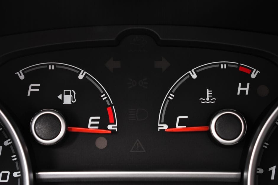
A coolant temperature sensor is a small thermistor that measures the engine coolant temperature and sends that data to the engine control unit. It threads directly into the engine block or cylinder head, where its tip sits in the coolant passage. As the thermistor’s resistance changes with temperature, the sensor produces a voltage signal the ECU can interpret. Most modern vehicles use a negative temperature coefficient (NTC) thermistor, meaning resistance decreases as temperature increases. The ECU applies a reference voltage (typically 5V) through a pull-up resistor, and the voltage drop across the sensor tells the ECU exactly how hot the coolant is.
The Role of the ECT Sensor in Engine Management
The ECT sensor is one of the most critical inputs for engine management. The ECU uses coolant temperature to calculate fuel injection pulse width — cold engines need a richer mixture to run smoothly, while warm engines require a leaner mixture for efficiency. Ignition timing is also advanced or retarded based on coolant temperature to prevent knock and optimize combustion. The idle air control valve adjusts idle speed based on coolant temperature, raising RPM during cold starts and lowering it once the engine reaches operating temperature. The cooling fan relay is triggered by the ECU when coolant temperature exceeds a threshold (typically around 200°F/93°C), and in automatic transmissions, the ECU modifies shift points and torque converter lockup based on engine temperature to protect the drivetrain during cold operation.
ECT Sensor vs. Coolant Temperature Sender vs. CTS: What’s the Difference?
These three terms are often used interchangeably, but they refer to different components. The ECT sensor (engine coolant temperature sensor) is a two-wire sensor that sends a variable voltage signal to the ECU for engine management. The coolant temperature sender is typically a one-wire unit that drives only the dashboard temperature gauge — it does not communicate with the ECU. The CTS (coolant temperature switch) is a binary on/off switch that activates the radiator fan or a warning light at a preset temperature. Some vehicles use a single sensor for both ECU and gauge functions, but most modern cars have separate components. Replacing the wrong one is a common DIY mistake — the gauge may still work while the ECU runs in open-loop mode, causing poor fuel economy and driveability issues.
Where Is the Coolant Temperature Sensor Located?
The ECT sensor is typically located in the engine block near the thermostat housing, in the cylinder head, or in the intake manifold coolant passage. On most inline engines, it sits near the front of the block where the upper radiator hose connects. On V-configuration engines, it is often found on the crossover pipe or in the intake manifold. The exact location varies by manufacturer — GM often places it in the intake manifold, Ford frequently uses the thermostat housing, and Toyota commonly mounts it in the cylinder head near the distributor. To locate it, follow the upper radiator hose to the engine block or look for a two-wire connector with a green or black plastic body. The coolant temperature sender for the gauge is usually nearby but has a single wire.
How the Coolant Temperature Sensor Communicates with the ECU
Understanding Thermistor Resistance vs. Temperature Curves
The ECT sensor operates on a predictable resistance curve. At 32°F (0°C), a typical NTC thermistor reads around 5,000 to 10,000 ohms. At 68°F (20°C), resistance drops to roughly 2,000 to 3,500 ohms. At 176°F (80°C), it falls to about 300 to 400 ohms. At 212°F (100°C), resistance is typically 150 to 200 ohms. The exact values vary by manufacturer, so always consult the factory service manual for your specific vehicle. The ECU reads the voltage drop across the sensor — when the engine is cold, resistance is high, voltage is high, and the ECU enriches the fuel mixture. As the engine warms, resistance drops, voltage falls, and the ECU leans out the mixture and advances timing.
Voltage Signal and Reference Voltage Explained
The ECU supplies a regulated 5V reference voltage to the ECT sensor through a pull-up resistor inside the ECU. The sensor’s variable resistance creates a voltage divider circuit. When the engine is cold, the sensor’s high resistance causes most of the voltage to drop across the sensor, so the ECU sees a high signal voltage (around 3.5–4.5V). When warm, the low resistance causes the voltage to drop to around 0.5–1.5V. The ECU continuously monitors this signal and compares it to expected values based on engine runtime and other sensor inputs. If the signal is implausible — for example, reading -40°F while the engine is hot — the ECU sets a diagnostic trouble code (P0115, P0116, P0117, or P0118) and may default to a fail-safe temperature value.
Open-Loop vs. Closed-Loop Operation
During cold starts, the ECU operates in open-loop mode, ignoring oxygen sensor feedback and using the ECT sensor to command a rich fuel mixture. Once the coolant temperature reaches a threshold (typically 140–160°F / 60–71°C), the ECU switches to closed-loop operation, using oxygen sensor data to fine-tune the air-fuel ratio. A faulty ECT sensor that reads too cold will keep the engine in open-loop indefinitely, causing rich running, poor fuel economy, and fouled spark plugs. A sensor that reads too hot will cause the ECU to lean out the mixture prematurely, leading to hard cold starts, hesitation, and potential engine damage.
Common Failure Symptoms of a Faulty Coolant Temperature Sensor
Poor Fuel Economy and Rich Running
When the ECT sensor fails and reads colder than actual temperature, the ECU enriches the fuel mixture continuously. This results in a noticeable drop in fuel economy — often 15–20% or more. You may also notice a strong fuel smell from the exhaust, black smoke during acceleration, and fouled spark plugs over time. The engine may run rough at idle because the mixture is too rich for the actual operating conditions.
Hard Cold Starts and Rough Idle
A failed ECT sensor that reads too hot will cause the ECU to lean out the mixture during cold starts. The engine will crank longer before firing, may stumble or stall immediately after starting, and will idle roughly until it warms up. In severe cases, the engine may not start at all in cold weather because the mixture is too lean to ignite.
Overheating or Cooling Fan Malfunction
If the ECT sensor fails and reads too cold, the ECU may never activate the cooling fan, causing the engine to overheat in traffic or at idle. Conversely, if the sensor reads too hot, the fan may run constantly, even when the
engine is cold. This wastes energy, puts unnecessary strain on the fan motor, and can drain the battery if the fan runs with the ignition off in some vehicles. A faulty sensor can also cause the temperature gauge to read incorrectly — either pegging at hot or staying at cold — which can lead to driver confusion and potential engine damage if overheating goes unnoticed.
Check Engine Light and Diagnostic Trouble Codes
A failing ECT sensor will almost always trigger the check engine light. Common codes include P0115 (ECT sensor circuit malfunction), P0116 (ECT sensor range/performance problem), P0117 (ECT sensor circuit low input — indicating a short or reading too hot), and P0118 (ECT sensor circuit high input — indicating an open circuit or reading too cold). These codes are stored in the ECU and can be retrieved with an OBD-II scanner. However, a sensor can be out of spec without triggering a code — the ECU only flags values that fall outside a plausible range, so a sensor that reads 20°F too cold may not set a code but will still cause driveability issues.
Erratic Temperature Gauge Behavior
If your dashboard temperature gauge fluctuates wildly, drops to zero while driving, or pegs at hot intermittently, the ECT sensor (or the separate sender) may be failing. A loose connection, corroded terminals, or internal sensor degradation can cause intermittent signal loss. This is especially dangerous because the gauge may show normal temperature while the engine is actually overheating, or vice versa. If the gauge behaves erratically, test the sensor immediately and inspect the wiring harness for damage.
Transmission Shift Problems
Since the ECU uses coolant temperature to adjust transmission shift points and torque converter lockup, a faulty ECT sensor can cause harsh or delayed shifts. The transmission may shift too early when cold (because the ECU thinks the engine is warm) or hold gears too long (because it thinks the engine is cold). This not only affects driveability but can also increase transmission wear over time.
How to Test a Coolant Temperature Sensor
Tools You Will Need
Testing an ECT sensor requires a digital multimeter (DMM) capable of reading resistance (ohms) and voltage (DC volts), a thermometer that can measure up to 212°F (100°C), a pot of boiling water, and the factory resistance specification table for your vehicle. You may also need a wiring diagram to identify the correct pins on the connector. A scan tool or OBD-II reader is helpful for reading live data and comparing the sensor reading to actual coolant temperature.
Visual Inspection First
Before testing electrically, inspect the sensor and its connector. Look for cracked or corroded terminals, damaged wires, oil or coolant contamination, and signs of physical damage to the sensor body. Check the connector for loose pins or spread terminals. Clean any corrosion with electrical contact cleaner and verify the connector locks securely. A poor connection can mimic a faulty sensor, so always rule out wiring issues first.
Resistance Test (Cold and Hot)
Disconnect the sensor and set your multimeter to resistance (ohms) mode. Measure the resistance across the two sensor terminals. Compare this reading to the factory specification for the current coolant temperature. For example, at 68°F (20°C), a typical GM sensor should read around 2,500 ohms, a Ford sensor around 3,000 ohms, and a Toyota sensor around 2,000 ohms. If the reading is significantly out of spec (more than 10–15%), the sensor is likely faulty. Next, heat a pot of water to boiling (212°F / 100°C) and carefully suspend the sensor tip in the water (do not submerge the connector). Measure the resistance again — it should drop to the hot specification (typically 150–250 ohms). If the resistance does not change smoothly or falls outside the spec, replace the sensor.
Voltage Test (Circuit Check)
With the sensor disconnected and the ignition on (engine off), measure the voltage at the connector harness side. You should see approximately 5V on one pin and ground on the other. If there is no voltage, check the ECU fuse, wiring, and ground connections. If voltage is present, reconnect the sensor and back-probe the signal wire with the engine running. As the engine warms up, the voltage should decrease smoothly from around 3.5V (cold) to about 1.0V (warm). A voltage that jumps erratically or stays fixed indicates a faulty sensor or wiring issue.
Live Data Scan Tool Test
Connect an OBD-II scanner and view live data for “Engine Coolant Temperature.” Compare the reading to the actual coolant temperature measured with an infrared thermometer on the thermostat housing or upper radiator hose. If the scanner reading differs by more than 10°F (5°C) from the actual temperature, the sensor is out of calibration. Also monitor the reading during a cold start — it should start near ambient temperature and rise steadily as the engine warms. A reading that jumps instantly to 200°F or stays at -40°F indicates a short or open circuit.
Replacement Cost and Procedure
OEM vs. Aftermarket Price Comparison
The cost of a coolant temperature sensor varies significantly by brand and vehicle. OEM sensors from dealerships typically range from $30 to $80 for most vehicles, while aftermarket sensors from brands like Denso, Bosch, Standard Motor Products, and Delphi range from $10 to $40. For luxury or performance vehicles, OEM sensors can cost $100 or more. Aftermarket sensors are often manufactured to the same specifications as OEM units and can be a cost-effective alternative, but quality varies — some cheap sensors use lower-grade thermistors that drift out of spec over time. For critical applications, many technicians recommend OEM or reputable aftermarket brands over generic no-name parts.
Labor Time and Total Cost
Replacing a coolant temperature sensor is a straightforward job that typically takes 30 to 60 minutes for a DIY mechanic. Labor costs at a shop range from $50 to $150 depending on the hourly rate and sensor accessibility. Total replacement cost (parts and labor) usually falls between $60 and $200 for most vehicles. If the sensor is located in a difficult position — such as behind the intake manifold or under the throttle body — labor time can increase to 1.5 to 2 hours, raising the total cost to $200–$300.
Step-by-Step Replacement Procedure
Start by ensuring the engine is cool to avoid burns from hot coolant. Disconnect the negative battery cable. Remove the electrical connector from the sensor by pressing the release tab and pulling straight off. Use a deep socket or wrench to unscrew the sensor counterclockwise — be careful not to damage the threads in the block. Some sensors may be tight due to corrosion; apply penetrating oil and allow it to soak before attempting removal. Once removed, compare the old sensor to the new one to ensure they are identical. Apply a small amount of thread sealant (if specified by the manufacturer) to the new sensor threads, being careful not to get sealant on the sensor tip. Thread the new sensor in by hand to avoid cross-threading, then tighten it to the factory torque specification (typically 15–20 ft-lb). Reconnect the electrical connector, reconnect the battery, and start the engine. Check for coolant leaks around the sensor and verify the temperature gauge and scan tool readings are accurate.
Bleeding the Cooling System
After replacing the sensor, you may need to bleed air from the cooling system, especially if you lost a significant amount of coolant during the swap. Run the engine with the radiator cap off and the heater set to maximum, allowing the thermostat to open and purge air bubbles. Top off the coolant as needed. Check for leaks after the engine reaches operating temperature and the cooling fan cycles on and off.
Material, Build Quality, and Compatibility
Materials and Construction
Quality coolant temperature sensors are constructed with a brass or stainless steel housing for corrosion resistance and thermal conductivity. The thermistor element is typically a ceramic bead or disc coated with epoxy or glass for protection against coolant exposure. The electrical connector is molded from high-temperature plastic that resists cracking and melting. OEM sensors use precision-matched thermistors with tight tolerance (±2–3% resistance accuracy), while cheaper aftermarket sensors may have looser tolerances (±5–10%), which can cause inaccurate readings and driveability issues. The threads are typically 1/8″ NPT, M12x1.5, or M14x1.5 depending on the vehicle — always verify thread size and pitch before purchasing a replacement.
Compatibility and Resistance Values by Manufacturer
Coolant temperature sensors are not universal — each manufacturer uses different resistance curves. GM sensors typically read 4,500–5,000 ohms at 32°F, 2,500 ohms at 68°F, and 185 ohms at 212°F. Ford sensors use a similar curve but with slightly different values: 3,700 ohms at 68°F and 200 ohms
at 212°F. Toyota sensors read approximately 2,000 ohms at 68°F and 150 ohms at 212°F. European manufacturers like BMW and Mercedes use their own proprietary curves that differ significantly from domestic brands. Always cross-reference the OEM part number or consult the factory service manual to ensure you purchase the correct sensor for your vehicle. Installing a sensor with the wrong resistance curve will cause incorrect temperature readings, poor fuel economy, and potential engine damage.
Choosing the Right Replacement Sensor
When selecting a replacement sensor, consider your vehicle’s age and your budget. For older vehicles with high mileage, a quality aftermarket sensor from a reputable brand is often sufficient and cost-effective. For newer vehicles still under warranty or with sensitive engine management systems, OEM sensors are recommended to ensure precise readings and avoid potential compatibility issues. Check customer reviews and look for sensors that include the correct connector and sealing ring. Some aftermarket sensors come with adapters for different connector styles — these should be avoided as they can introduce resistance and signal integrity issues. If you are unsure, consult a professional technician or use the OEM part number to find a direct replacement.
Common Mistakes to Avoid
One of the most common mistakes is replacing the coolant temperature sender instead of the ECT sensor — they look similar but serve different functions. Another mistake is over-tightening the sensor, which can crack the housing or strip the threads in the engine block. Using thread sealant on the sensor tip can insulate the thermistor and cause inaccurate readings. Finally, failing to bleed the cooling system after replacement can leave air pockets that cause false temperature readings and overheating. Always double-check that you have the correct sensor for your vehicle’s make, model, and engine code before installation.
Coolant Temperature Sensor vs. Related Components
Intake Air Temperature Sensor
The intake air temperature (IAT) sensor measures the temperature of incoming air and is often confused with the ECT sensor because they use similar thermistor technology. However, the IAT sensor is located in the intake manifold or air intake duct, not in the coolant passage. The ECU uses both sensors to calculate air density and fuel delivery. A faulty IAT sensor can cause similar symptoms to a bad ECT sensor — poor fuel economy, rough idle, and hard starting — but it will not affect cooling fan operation or transmission shift points. If you suspect a temperature sensor issue, check both sensors and their respective wiring.
Thermostat
The thermostat is a mechanical valve that regulates coolant flow to maintain engine operating temperature. A stuck-open thermostat causes the engine to run cold, which can mimic a faulty ECT sensor that reads too cold. A stuck-closed thermostat causes rapid overheating, which can damage the ECT sensor and other components. When diagnosing temperature-related issues, always verify thermostat operation before replacing the ECT sensor. A simple test is to feel the upper radiator hose — it should become hot only after the engine reaches operating temperature, indicating the thermostat has opened.
Radiator Fan Switch
The radiator fan switch (or fan control module) is a separate component that directly controls the cooling fan based on coolant temperature. On some vehicles, the fan switch is a standalone thermostatic switch threaded into the radiator or thermostat housing. On others, the ECU controls the fan using the ECT sensor signal. If your fan does not activate but the temperature gauge reads normally, the fan switch or fan relay may be faulty rather than the ECT sensor. Test the fan by jumping the relay or applying power directly to confirm the fan motor works before replacing any sensors.
Coolant Temperature Gauge and Sender
The dashboard temperature gauge is driven by a separate sender unit, not the ECT sensor. The sender is a one-wire thermistor that varies resistance to move the gauge needle. If your gauge reads incorrectly but the engine runs fine and the scan tool shows correct coolant temperature, the sender is faulty — not the ECT sensor. Conversely, if the gauge reads normal but the engine runs poorly and the scan tool shows an implausible temperature, the ECT sensor is the culprit. Understanding this distinction saves time and money during diagnosis.
Preventive Maintenance and Best Practices
When to Replace the Coolant Temperature Sensor
There is no set service interval for coolant temperature sensors — they are designed to last the life of the vehicle. However, sensors exposed to contaminated coolant, extreme heat cycles, or electrical surges may fail prematurely. If you are replacing the thermostat, water pump, or radiator, it is a good opportunity to inspect the ECT sensor and replace it if it shows signs of corrosion or damage. Some technicians recommend replacing the sensor preventatively at 100,000 miles as part of a cooling system overhaul, as the cost is low compared to the potential engine damage from a failure.
Maintaining the Cooling System
Regular coolant flushes at the manufacturer-recommended intervals (typically every 30,000–50,000 miles) help prevent sensor corrosion and buildup. Use the correct coolant type specified for your vehicle — mixing incompatible coolants can cause chemical reactions that damage the sensor and other cooling system components. Check the coolant level regularly and inspect for leaks around the sensor and thermostat housing. A low coolant level can cause the sensor to read incorrectly because it may not be fully submerged in coolant.
Diagnostic Tips for Intermittent Issues
Intermittent ECT sensor problems are the most challenging to diagnose. A sensor that works fine when cold but fails when hot, or vice versa, may have a cracked solder joint or a thermistor that drifts with temperature. Use a heat gun to warm the sensor while monitoring resistance — if the resistance jumps erratically, the sensor is failing. Also inspect the wiring harness for chafing, corrosion, or loose connections that can cause intermittent signal loss. A wiggle test — gently moving the wiring while the engine runs — can help identify loose connections. If the problem is intermittent and all tests pass, consider replacing the sensor anyway, as it is a relatively inexpensive part.
Frequently Asked Questions
Can I drive with a faulty coolant temperature sensor?
You can drive short distances with a faulty ECT sensor, but it is not recommended. The engine may run rich or lean, causing poor fuel economy, increased emissions, and potential damage to the catalytic converter and spark plugs. If the sensor fails in a way that prevents the cooling fan from activating, the engine can overheat and suffer severe damage. If the check engine light is on and you suspect the ECT sensor, have it diagnosed and replaced as soon as possible.
How long does a coolant temperature sensor last?
Most coolant temperature sensors last 100,000 miles or more. However, their lifespan depends on coolant quality, operating conditions, and electrical system health. Sensors in vehicles that frequently tow, operate in extreme temperatures, or have contaminated coolant may fail earlier. Regular cooling system maintenance helps extend sensor life.
Will a bad coolant temperature sensor cause a car to overheat?
Yes, a bad ECT sensor can cause overheating if it fails in a way that prevents the ECU from activating the cooling fan. If the sensor reads too cold, the ECU will not command the fan to turn on, even when the engine reaches dangerous temperatures. This is one of the most serious failure modes and can lead to head gasket failure or engine warping if not addressed promptly.
Can I clean a coolant temperature sensor instead of replacing it?
In some cases, cleaning the sensor tip with electrical contact cleaner or a soft brush can remove buildup and restore function. However, if the thermistor itself is damaged or the sensor is out of calibration, cleaning will not help. Since sensors are relatively inexpensive, replacement is usually the better option if cleaning does not resolve the issue.
What is the difference between a 2-wire and 1-wire coolant temperature sensor?
Understanding is the difference between a 2-wire and 1-wire coolant temperature sensor?
A 2-wire sensor has a dedicated ground and signal wire, providing a more accurate and stable reading to the ECU. A 1-wire sensor uses the sensor body as ground and is typically used for the dashboard gauge sender. The ECT sensor for engine management is almost always a 2-wire design, while the gauge sender is usually 1-wire. Some vehicles use a 3-wire sensor that combines both functions with a shared ground.
Conclusion
The coolant temperature sensor is a small but critical component that directly influences engine performance, fuel economy, emissions, and cooling system operation. Understanding how it works, recognizing the symptoms of failure, and knowing how to test and replace it can save you time, money, and potential engine damage. Whether you are a DIY mechanic or a professional technician, having a solid grasp of ECT sensor diagnostics is essential for accurate troubleshooting.
This guide has covered the full scope of the coolant temperature sensor — from its electrical operation and communication with the ECU to failure symptoms, testing procedures, replacement costs, and compatibility considerations. By following the diagnostic steps outlined here, you can confidently determine whether your coolant temperature sensor is functioning correctly or needs replacement. Remember to always consult your vehicle’s factory service manual for specific specifications and procedures,
and to use quality parts from reputable manufacturers. A properly functioning coolant temperature sensor ensures your engine runs efficiently, protects against overheating, and provides accurate information to the ECU for optimal performance in all driving conditions.
Whether you are troubleshooting a check engine light, addressing poor fuel economy, or performing routine cooling system maintenance, the knowledge gained from this guide will help you make informed decisions. If you are ever in doubt about a diagnosis, consult a professional technician who has access to factory diagnostic equipment and service information. The coolant temperature sensor may be a small component, but its role in engine management is indispensable — keeping it in good working order is one of the simplest and most effective ways to maintain your vehicle’s health and longevity.