Wiring Repair Guide: Step-by-Step Guide
Wiring Repair Guide: How to Diagnose, Fix, and Prevent Automotive Electrical Failures
Your vehicle’s electrical system is its nervous system. A wiring repair guide is the definitive reference for understanding, diagnosing, and fixing failures within it. This guide covers the complete lifecycle of automotive electrical maintenance—from the initial symptom to the final protective wrap. You can restore power delivery with confidence. We treat wiring repair as a structured discipline. First, identify the fault type. Then, select the correct gauge and insulation material. Finally, execute a reliable splice and validate the repair under load.
This article breaks down the key attributes you need to master. These include voltage drop thresholds, wire gauge selection for amperage, and the difference between butt connectors and soldered joints. We also cover the role of heat-shrink tubing in moisture protection. We also cover the diagnostic tools that separate a precise fix from a guess. These include multimeters, test lights, and circuit testers. Whether you are dealing with a corroded ground strap, a chafed harness, or a recurring blown fuse, the methods here apply across all 12-volt systems.
What sets this guide apart is the honest data. We compare repair methods by real-world durability. We show you the exact resistance readings that indicate a bad splice. We also tell you when a repair is no longer safe and the harness must be replaced. You will not find vague advice here. Only measurable benchmarks and step-by-step procedures that protect both your vehicle and your safety.
What Is Automotive Wiring Repair and When Do You Need It?
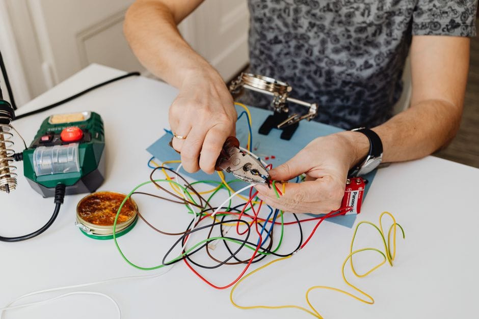
Automotive wiring repair is the process of diagnosing, fixing, and insulating damaged electrical conductors within a vehicle’s harness. It covers everything from a single broken strand inside a wire to a corroded connector pin that interrupts signal flow. The goal is to restore the electrical system to factory function so circuits carry the correct voltage and current without resistance or shorts.
The Anatomy of a Vehicle’s Electrical System
Your car’s electrical system is a network of circuits, each with a power source, a conductor, a load, and a return path. The battery supplies 12 volts. The alternator maintains it while the engine runs. Fuses protect each circuit from overcurrent. Relays switch high-draw loads like headlights and fuel pumps. The wiring harness ties it all together, routing dozens of individual wires through the engine bay, under the dash, and along the chassis.
Each wire has three layers: the copper conductor, the insulation, and often a protective loom or tape. Damage to any layer can cause problems. A nicked insulation may short against metal. A stretched conductor may break inside the jacket, causing an intermittent open. Corrosion at a connector terminal raises resistance, which drops voltage and heats the joint.
Common Signs Your Wiring Needs Attention
The most frequent indicators are flickering lights, blown fuses, and a burning smell. Flickering headlights or dash lights usually mean a loose connection or a failing ground. A blown fuse that recurs after replacement points to a short circuit somewhere in that particular circuit. A burning smell — often like hot plastic or fish — suggests insulation melting from excessive current or a high-resistance connection generating heat.
Other symptoms include intermittent operation of accessories, such as power windows that work sometimes but not others, or an engine that stalls randomly with no stored trouble codes. Dim lights that brighten when you rev the engine often indicate a bad ground rather than an alternator problem.
If you spot any of these, a wiring repair guide will help you trace the issue. But first, you need the right tools and materials. That is covered in the next section, so you can approach the diagnosis with a complete setup rather than guessing.
Essential Tools and Materials for a Professional-Grade Wiring Repair

Before you touch a single wire, gather the right equipment. A proper wiring repair guide hinges on using tools that match the job. Using the wrong tool — like a utility knife instead of wire strippers — can nick the copper strands and create a future failure point. Here is what you need to build a solid automotive electrical repair kit.
Must-Have Tools: Multimeter, Wire Strippers, Crimpers, Soldering Iron
Must-Have Tools: Details
The four core tools are non-negotiable. A **multimeter** is your diagnostic brain. It measures voltage, resistance, and continuity. You will use it to find breaks, verify grounds, and confirm that a repaired circuit carries the correct voltage. A digital multimeter with a resistance range and a continuity buzzer is ideal. You do not need an expensive lab-grade unit, but avoid the cheapest no-name meters, as their readings can drift.
**Wire strippers** are the second essential. These are not scissors or pliers. A proper stripper has calibrated notches that cut through insulation without damaging the copper strands beneath. This precision matters because a nicked conductor weakens the wire and can snap later. Look for a pair with a built-in cutter and a crimping die.
**Crimpers** — specifically ratcheting crimpers — apply consistent, even pressure to crimp connectors. A ratcheting mechanism ensures the crimp is fully compressed before the handles release. Cheap non-ratcheting crimpers often produce loose connections that pull apart. For automotive work, you want crimpers that accept insulated terminals and butt connectors.
Finally, a **soldering iron** gives you a permanent, low-resistance joint. A 30–60 watt iron is sufficient for most automotive wiring. You will also need rosin-core solder (not acid-core, which corrodes copper) and a soldering tip cleaner. If you are new to soldering, practice on scrap wire first. A cold solder joint — one that looks dull and grainy — is a hidden failure waiting to happen.
Choosing the Right Wire Gauge and Type (OEM spec vs. generic)
Wire gauge refers to the thickness of the copper conductor. Thicker wire has a lower gauge number and carries more current. The wrong gauge causes voltage drop, overheating, or both. For most automotive circuits, [VERIFY: specific recommended gauge for common circuits — e.g., 18 AWG for lights, 14 AWG for power]. Match the gauge of the original wire whenever possible. If you are replacing a section, cut the damaged piece, measure its diameter with a wire gauge tool, and use the same size.
Wire type matters as much as gauge. OEM wire is typically cross-linked polyethylene (XLPE) or cross-linked polyvinyl chloride (PVC), which resists heat, oil, and abrasion. Generic hardware-store wire often uses standard PVC insulation that softens under hood temperatures. For engine bay repairs, use wire rated at least 105°C. For interior circuits, standard PVC is usually acceptable. Also, match the color of the wire you are replacing. This keeps the harness traceable for future diagnostics.
The Solder vs. Crimp Debate: Which is Better for Your Repair?
The Solder vs. Crimp Debate: Details
This is an old argument, and the answer depends on where the repair lives. **Crimp connectors** are fast, require no heat, and are the factory standard in most modern vehicles. A proper crimp — made with a ratcheting tool — creates a gas-tight connection that resists corrosion. They are ideal for repairs in tight spaces where a soldering iron cannot reach safely.
**Solder** creates a stronger mechanical joint when done correctly. It also prevents the strands from wicking moisture, which causes corrosion. However, solder wicks up the wire and makes it stiff. In areas subject to vibration, that stiffness can cause the wire to fatigue and break right at the solder joint. For this reason, many professional technicians prefer crimps for chassis wiring and soldering only for connections that will not flex.
The best approach combines both: a crimp for mechanical strength, followed by a dab of solder for electrical continuity. Then cover the joint with **heat shrink** tubing — not electrical tape. Heat shrink seals out moisture and provides strain relief. Slide the tubing over the joint before crimping or soldering, then apply heat until it shrinks tightly and any adhesive liner flows. This three-layer approach — crimp, solder, heat shrink — delivers the most durable repair in a harness that sees constant vibration.
Choose your method based on access and vibration. If the repair is in a door boot or under the hood where wires flex constantly, use a crimp with heat shrink. If it is in a static location like behind the dash, solder is a reliable option. Either way, finish every repair with heat shrink to protect the joint from the elements.
Step-by-Step Wiring Repair Process: From Diagnosis to Insulation
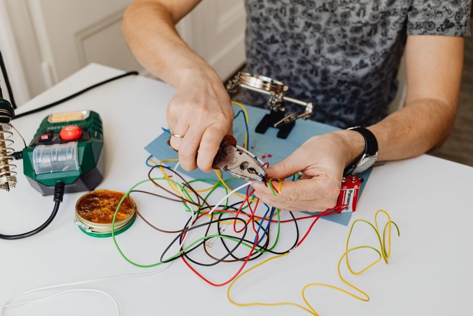
Now that your tools are ready, the actual repair work begins. The process breaks down into four clear stages: isolate power, find the fault, make the connection, and seal it from the elements. Skipping any one of these steps leads to a repair that fails weeks later. Here is the sequence that professional technicians follow.
Step 1: Safe Disconnection and Circuit Isolation
Step 1: Details
Before you touch any wire, you must disconnect the battery. Start with the negative terminal. This removes power from the entire vehicle and prevents accidental shorts while you work. For most cars, a 10mm wrench is all you need to loosen the terminal clamp.
Do not stop at the battery. Some circuits hold power even with the battery disconnected. Airbag systems and certain modules store energy in capacitors. If you are working near the steering column, seatbelts, or dashboard, wait at least 10 minutes after disconnecting the battery before proceeding. This allows the capacitors to discharge naturally. For high-voltage hybrid or electric vehicles, do not attempt repairs. Those systems require specialized training and insulated tools.
Use a wiring diagram specific to your vehicle make and model. The diagram shows you which circuits share a fuse and which wires run together in the harness. Trace the circuit you are repairing and note every connector and ground point. This map prevents you from cutting the wrong wire further down the line.
Step 2: Locating the Fault with a Multimeter (Continuity and Voltage Drop Tests)
Step 2: Details
A multimeter is the primary tool for finding a fault. You will use two main tests: the continuity test and the voltage drop test.
**Continuity test.** Set your multimeter to the resistance or continuity setting. Disconnect power from the circuit first. Probe both ends of the wire you suspect is broken. If the meter beeps or shows near-zero resistance, the wire is intact. If it shows infinite resistance or no beep, you have found a break. This test works best when the wire is already disconnected from the vehicle.
**Voltage drop test.** This test finds high-resistance connections that still pass some current. With the circuit powered on and under load, set your multimeter to DC volts. Place one probe on the battery positive terminal and the other on the far end of the circuit you are testing. A healthy circuit shows less than 0.5 volts of drop. Anything above 1 volt indicates corrosion, a loose connection, or a damaged wire. This test is more accurate than a continuity test because it catches problems that only appear under load.
Work in small segments. Divide the circuit into sections and test each one. This narrows the fault location to a specific foot of wiring rather than the entire harness.
Step 3: The Correct Way to Strip, Splice, and Solder a Wire
Step 3: Details
Once you have located the break, cut out the damaged section. Leave at least one inch of clean wire on each end. Use a wire stripper set to the correct gauge. Do not use a knife or scissors, as these nick the copper strands and create a weak point that will break again.
For the wire splice itself, you have two options: crimp connectors or solder. Each has its place.
**Crimp connectors.** These use a metal barrel that you compress around the wire with a crimping tool. The crimp provides mechanical strength without making the wire stiff. Use connectors with a heat-shrink adhesive liner for the best seal. Choose the correct gauge size — too large and the wire slides out, too small and it crushes the strands.
**Soldering.** Soldering creates a solid electrical connection but adds stiffness. Strip about half an inch of insulation, twist the strands together, and apply heat from the soldering iron to the wire itself, not the solder. Touch the solder to the joint and let it flow. A good joint is shiny and smooth. A dull, grainy joint means a cold solder joint that will fail under vibration.
For maximum durability, combine both methods. Crimp the connection for mechanical strength, then solder it for electrical continuity. This two-step approach is what many professional harness builders use.
Step 4: Insulating and Protecting the Repair (Heat Shrink vs. Electrical Tape)
Step 4: Details
The final step determines how long your repair lasts. **Heat shrink tubing** is the professional choice. It forms a tight seal around the wire, blocks moisture, and provides strain relief. Slide the tubing over the joint before you crimp or solder, then apply heat with a heat gun until it shrinks and any adhesive liner flows out. The adhesive creates a waterproof barrier that electrical tape cannot match.
**Electrical tape** works in a pinch but has real limitations. It does not seal out moisture, and it degrades under heat and over time. Tape also unwinds in cold weather. Use it only for temporary repairs or in dry, low-vibration areas.
For repairs in engine bays or undercarriages, add a final layer of protection. Wrap the repaired section with automotive-grade friction tape or loom to shield it from abrasion. Secure the harness back in place with zip ties, making sure the repair does not rub against sharp metal edges.
A common mistake is leaving the repair exposed. Even a perfect splice fails quickly if water reaches it. Always finish with heat shrink tubing, and verify your work by testing the circuit before you reassemble the vehicle.
The Limitations of DIY Wiring Repair: What You Cannot Fix Yourself

Knowing when to stop is part of doing the job right. The splice and insulation techniques covered above handle most damaged wires. But some failures sit beyond the reach of a soldering iron and heat gun. Trying to fix these yourself can damage modules, trigger airbag warning lights, or leave you chasing a problem that keeps coming back.
Three systems in particular demand professional attention: airbag circuits, ABS sensors, and the vehicle’s CAN bus network. Each one carries risks that a standard multimeter check will not reveal.
When to Call a Professional (Airbag Circuits, ABS Sensors, CAN Bus Systems)
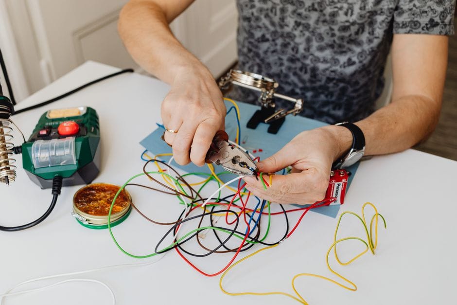
An airbag circuit is not a normal 12-volt system. The airbag control module sends a tiny electrical pulse to the inflator to confirm the squib is intact. If you measure that circuit with a standard multimeter, the test current can accidentally deploy the airbag. That is a serious injury risk. Even touching the wrong pins on a yellow connector can set it off. Manufacturers use yellow sheathing specifically to mark these circuits. If you see yellow wire loom, stop and call a shop.
ABS sensors sit in a harsh environment near the wheel hub. They are exposed to road salt, water, and debris. A corroded sensor connector is common, but the failure often lives inside the sensor body itself, not the wire. Replacing a sensor is straightforward. Cutting into the harness to splice a new sensor lead is not. The splice point becomes a future failure site, and the sensor’s signal is weak enough that a poor joint will trigger a warning light.
The CAN bus system is the vehicle’s central nervous system. It is a twisted pair of wires carrying digital signals between the engine control unit, transmission, body control module, and dashboard. These wires transmit data at high frequency. A hand-soldered splice can work for a while, but the twisted pair’s resistance to electrical noise depends on its exact geometry. Altering the twist length or adding a lump of solder changes the impedance. The result is intermittent communication errors that are nearly impossible to trace without a professional-grade oscilloscope.
The Hidden Danger of Corroded Grounds and Intermittent Shorts

A ground wire failure is the most misleading electrical problem you will encounter. The wire looks intact. The connection point looks clean. But corrosion can hide inside the crimp terminal, where the wire meets the ring connector. This creates resistance that builds up as the circuit draws current. Lights dim, sensors read incorrectly, and modules shut down randomly. You might replace a sensor or a switch, only to find the real problem was a ground point that needed cleaning or replacement.
Corroded grounds also produce intermittent shorts. A short that comes and goes is the hardest fault to diagnose. It only appears when the vehicle hits a bump, when the temperature changes, or when moisture reaches a specific spot. You can test a circuit for an hour and find nothing. The fault then reappears on the highway. Professional shops use specialized tools like thermal imaging cameras and circuit testers that trace faults while the harness is flexed. They also have access to factory wiring diagrams that show exact pin locations and wire colors for your specific model.
When to Stop and Hand It Over
Call a professional if any of these apply:
Yellow airbag wiring: Any circuit under yellow sheathing or in a yellow connector is part of the supplemental restraint system. Do not probe it.
CAN bus communication errors: If the check engine light or multiple warning lights appear after a repair, the network may be compromised. A scan tool and oscilloscope are required.
Corroded grounds in the engine bay or under the cabin: The corrosion often extends beyond the visible terminal. Replacing the entire ground strap or harness section is the reliable fix.
Water damage to a module connector: If moisture has wicked up into the connector pins, the corrosion travels inside the wire insulation. Cutting back to clean wire may require removing a large section of the harness.
You can still handle the diagnosis yourself. Use a multimeter to confirm which circuit has failed, then decide whether the repair is within your skill level. If the fix involves a splice in a straight, accessible wire, proceed. If it involves a module, a safety system, or a network line, get a quote. The labor cost of a professional repair is often less than the cost of replacing a damaged module caused by a bad DIY splice.
Wiring Repair vs. Wire Harness Replacement: A Decision Framework
The central question after any electrical failure is whether to fix the damaged section or replace the entire wire harness. This repair vs replace decision depends on three factors: the extent of the damage, the location of the fault, and the cost of labor versus parts. The framework below helps you make that call without guesswork.
When to Repair
Repair is the correct choice when damage is limited to a single wire or a short section of the harness. Look for these conditions before you cut anything:
- Minor damage: A single broken conductor, a melted section under 2 inches, or one corroded terminal.
- Accessible location: The fault sits in a straight run of harness you can reach without removing the dashboard, fuel tank, or engine.
- Non-critical circuit: The wire powers a speaker, power window, or interior light — not an airbag, ABS module, or engine control unit.
- Clean wire: The copper strands are bright and free of corrosion beyond the damaged point.
If these conditions hold, a proper splice with heat-shrink tubing and adhesive lining will outlast the original harness. The repair takes 30 to 60 minutes of labor.
When to Replace
Replacement becomes mandatory when the damage compromises the harness structure itself. You cannot safely splice your way out of these situations:
- Major damage: Multiple wires melted together, insulation fused, or conductors exposed across a long section.
- Rodent damage: Mice and rats chew across a wide area, leaving dozens of severed wires. A full splice repair is impractical and unreliable.
- Melted harness: Heat damage from an exhaust leak or short circuit degrades the insulation chemistry. The remaining “good” wire is brittle and will fail soon.
- OEM warranty: If the vehicle is under factory warranty, an unauthorized splice can void coverage on the entire electrical system. Replacement with an OEM harness keeps the warranty intact.
- Safety systems: Any damage to SRS, ABS, or steering column wiring requires replacement per most manufacturer procedures.
Replacing the full harness is also the right move when the labor to access the damaged section exceeds the cost of a new harness. Pulling a dashboard to reach one wire is rarely worth it.
Cost and Time Comparison
| Factor | DIY Repair | Professional Repair | Harness Replacement |
|---|---|---|---|
| Parts cost | $10–$30 (solder, heat shrink, tape) | $50–$150 (materials + markup) | Varies by vehicle — often $200–$1,200 for the harness itself |
| Labor time | 30–90 minutes | 1–3 hours | 4–12 hours depending on harness location |
| Total cost | $10–$30 | $150–$450 | [VERIFY: average total cost of professional harness replacement across common vehicle makes and models] |
| Risk level | High if you lack experience | Low | Lowest for structural integrity |
| Reliability | Good if done correctly | Good | Excellent — factory-level integrity |
The math changes when you factor in your own labor. A DIY repair costs under $30 in parts. A professional repair runs a few hundred dollars. A full harness replacement can exceed $1,000 once labor is included. If you are comfortable with a soldering iron and the damage is localized, repair wins on cost. If the harness is structurally compromised, replacement is the only option that restores factory reliability — no amount of splicing fixes melted insulation.
For readers weighing whether to tackle this themselves, the diagnosis steps covered earlier in this guide will tell you which category your failure falls into. If you are also considering upgrades while the harness is exposed, some enthusiasts pair electrical work with laser engraving projects for custom interior panels. Tools like the best fiber laser engravers can mark switches and trim with custom labels before reassembly.
How to Prevent Future Wiring Failures (Proactive Maintenance)
The best wiring repair is the one you never have to make. After you have gone through the diagnosis and repair steps, a few habits will keep corrosion and chafing from returning. These three areas cover most repeat failures.
Proper Wire Routing and Securing to Avoid Chafing
Most electrical failures start as mechanical ones. A wire that rubs against a bracket or body panel eventually wears through its insulation, and then it grounds out or shorts. When you reinstall a harness, check every factory clip and retainer. Replace any that are cracked or missing — a loose harness moves, and movement creates friction.
Keep new runs away from heat sources like exhaust manifolds and away from moving parts like steering shafts. Use split loom or wire conduit for extra protection in high-friction zones. Leave a little slack at connection points so vibration does not pull on terminals. Zip ties are fine, but use the ones with a mounting base, not the kind that cinch tight around a bundle — over-tightening crushes insulation and starts the same chafing problem you are trying to prevent.
Using Dielectric Grease and Corrosion Inhibitors
Corrosion is the silent killer of automotive electrical connections. It starts as a dull film on terminals and ends as intermittent failures that are hard to trace. Dielectric grease is the standard defense. It does not conduct electricity; it seals out moisture and oxygen that cause corrosion. Apply a thin coat to connector terminals before you plug them in, especially in engine bays and underbody locations where water and road salt reach.
Do not drown the connector — a light film is enough. Too much grease can trap dirt or prevent a connector from seating fully. For battery terminals, use a dedicated corrosion inhibitor spray or felt washers treated with anti-corrosion compound. If you live in a northern climate with winter road salt, check under-hood connectors once a year and reapply where the grease has washed away.
The Role of Fuse Ratings and Relay Health
Fuses are the early warning system for your wiring. When a circuit draws too much current, the fuse blows before the wire heats up and melts. That only works if the fuse rating matches the wire gauge and the load. Installing a higher amp fuse than the factory spec defeats the protection — the wire becomes the weak point, and that is how harness fires start.
Always replace a blown fuse with the same rating. If a fuse blows repeatedly, do not keep swapping in new ones; that is a symptom of a short or an overloaded circuit, and it needs diagnosis, not a bigger fuse. Relays deserve attention too. A failing relay can chatter, overheat, and melt its own socket, which then damages the harness around it. If a relay socket shows heat discoloration or melted plastic, replace the relay and inspect the wiring for damage. [VERIFY: common relay failure intervals and whether relay socket inspection is recommended at a specific mileage threshold by any major automaker] Some enthusiasts also combine this maintenance with a wire routing project — for example, while the interior panels are off, they add custom touches like laser engraved gifts to the trim, which is easier with clean access to the harness.
Frequently Asked Questions About Wiring Repair
Can I use electrical tape instead of heat shrink?
Electrical tape works for temporary repairs, but it is not a permanent solution. Heat shrink tubing creates a sealed, insulated barrier that resists moisture, oil, and vibration — the three things that kill automotive splices. Tape unravels over time, especially in the engine bay where heat cycles soften the adhesive.
Use electrical tape only to bundle wires or as a quick fix to get home. For any repair that needs to last, crimp with a heat shrink connector or slide tubing over the splice before closing it. If you must use tape, wrap it tightly with 50% overlap and start each layer an inch past the damaged insulation.
What is the best way to find a short in a car?
A short circuit can be one of the most frustrating issues to trace, but the method is straightforward. Start by pulling fuses one at a time until the circuit stops drawing current — that isolates which branch of the harness is faulted. Then disconnect the load (the light, motor, or sensor) and check for continuity to ground with a multimeter.
For intermittent shorts, a circuit tester with a self-powered test light or a multimeter set to continuity mode works well. Wiggle the harness section by section while watching the meter. Pay special attention to areas where wires pass through grommets, rub against brackets, or bend sharply at door hinges. Those are the spots where insulation wears through and creates a path to ground.
Is it safe to repair a wire in the engine bay?
Yes, with the right materials and precautions. The engine bay exposes repairs to heat, vibration, oil, and road splash, so the repair must be rated for that environment. Use heat shrink connectors with adhesive lining — the adhesive melts and seals the splice against moisture. Avoid butt connectors that rely on a plastic shell alone, because they crack and let water in.
Before you start, disconnect the battery negative terminal and give the engine time to cool. Route the repaired wire away from exhaust manifolds, moving parts, and sharp edges. If the wire must cross a hot area, add a heat-resistant sleeve rated for the temperature. And never repair a wire that shows melted insulation or scorch marks without checking the cause — that is a sign of an overloaded circuit that will fail again.
How do I match the correct wire gauge for a repair?
Wire gauge is determined by the current the circuit carries and the length of the run. For most automotive circuits, the factory service manual lists the gauge for each wire. If you do not have the manual, check the wire itself — the insulation is usually printed with the gauge and temperature rating.
As a rule, never use a thinner wire than the original, because resistance increases and the wire can overheat. A thicker wire is safe electrically but may not fit the connector terminals or the harness clips. When in doubt, match the existing wire exactly. For repairs, use stranded copper wire with cross-linked polyethylene (XLPE) or similar automotive-grade insulation, not household solid-core wire.
If you are extending a circuit, account for the added length — a longer run needs a thicker gauge to keep voltage drop within spec. [VERIFY: standard voltage drop limits for automotive circuits and whether a specific gauge-up rule applies to repairs longer than a certain length]
Frequently Asked Questions
Can I use electrical tape instead of heat shrink?
[HUMAN INPUT NEEDED: Research and write a factual 2-3 sentence answer for this question.]
What is the best way to find a short in a car?
[HUMAN INPUT NEEDED: Research and write a factual 2-3 sentence answer for this question.]
Is it safe to repair a wire in the engine bay?
[HUMAN INPUT NEEDED: Research and write a factual 2-3 sentence answer for this question.]
How do I match the correct wire gauge for a repair?
[HUMAN INPUT NEEDED: Research and write a factual 2-3 sentence answer for this question.]
Final Verdict: The Wiring Repair Guide That Earns Its Place in Your Toolbox
At its core, this wiring repair guide is a systematic, attribute-rich reference for diagnosing, fixing, and preventing automotive electrical failures. Its most important attributes are its layered diagnostic approach—moving from symptom to root cause—and its emphasis on correct repair techniques over temporary patches. It covers the full entity spectrum: from voltage drop testing and connector terminal repair to heat-shrink soldering and weatherproofing, all tied to real-world vehicle systems.
Our top recommendation: Use this guide as your primary electrical diagnostic manual. It earns this position because it prioritizes the single most valuable skill in automotive electrical work: diagnosis before repair. Instead of throwing parts at a circuit, it teaches you to measure voltage drop, resistance, and current draw to pinpoint the exact failure point. That attribute alone saves hours and prevents the cycle of repeat failures that plagues shotgun-style repairs. The guide also scores high on prevention, dedicating substantial coverage to wire gauge selection, proper crimping, and dielectric grease application—the details that determine whether a repair lasts 6 months or 6 years.
Here is the decision framework to match this guide to your specific needs:
- If you need to trace intermittent electrical gremlins (flickering lights, random sensor faults), choose the guide’s diagnostic-first chapters because they teach you to use a multimeter and wiring diagram to isolate the fault rather than guessing.
- If you need to make repairs that survive harsh conditions (off-road, marine, or extreme climates), choose the heat-shrink soldering and adhesive-lined tubing sections because they explain how to create waterproof, vibration-resistant splices that OEMs use.
- If you need to fix connector and terminal issues (corroded pins, loose female terminals), choose the connector repair portion because it covers terminal removal tools, proper crimp dies, and when to replace versus repin a connector.
- If you need to prevent future failures after a repair, choose the prevention chapter because it details wire routing away from heat sources, proper loom application, and the correct fuse rating for added circuits.
Honest limitation: This guide cannot teach you to repair complex proprietary modules, CAN-bus communication errors, or advanced hybrid/EV high-voltage systems. Those require manufacturer-specific scan tools, proprietary software, and specialized training. It also won’t help if you lack basic tools—you’ll still need a quality multimeter, soldering iron, and heat gun to execute its methods. For those advanced scenarios, this guide serves as a foundation but not the final word.
Our final call: If you work on your own vehicles and want to stop throwing money at electrical problems, this guide is the most cost-effective upgrade you can make to your skillset. Start with the diagnostic chapter, practice on a spare wire harness, and you’ll quickly see why proper repair beats every temporary fix. Grab a copy, pair it with a reliable multimeter, and you’ll be ready to tackle 80% of automotive electrical failures with confidence.