Fuse Box Diagram Guide: Complete Guide
Fuse Box Diagram Guide: How to Read, Decode, and Troubleshoot Your Vehicle’s Electrical Center
A fuse box diagram is the master key to your vehicle’s electrical center — the coded map that translates a maze of colored wires, numbered slots, and plastic relays into a readable language of circuits, amperage ratings, and protected systems. Every car, truck, and SUV on the road today relies on this unassuming schematic to route power from the battery to everything from your headlights to your fuel pump. Without it, a single blown fuse becomes a frustrating guessing game that can leave you stranded or, worse, lead to costly electrical damage.
In this guide, we’ll break down exactly how to read, decode, and troubleshoot your fuse box diagram — covering the three main fuse box locations (under-hood, interior, and trunk-mounted), the critical differences between blade-type and mini-fuse formats, and how to match amperage ratings to the correct wire gauge. You’ll learn how to interpret the cryptic abbreviations like ABS, ECM, and IGN, spot the early warning signs of a failing relay, and use a simple multimeter to trace a short circuit without burning out your electrical system. This isn’t just theory — we’ve included real-world fuse box layouts from popular 2015–2025 models, a color-coded amperage reference table, and a step-by-step troubleshooting decision tree that works whether you’re driving a Ford F-150 or a Honda Civic.
Most online guides stop at “check the diagram and replace the fuse.” We go further. We’ll show you how to identify parasitic draws, why a fuse can blow repeatedly even after replacement, and when a DIY fix crosses the line into “call a professional.” By the end, you’ll have the confidence to diagnose 80% of common electrical faults yourself — and know exactly when to hand the keys to an auto electrician. Let’s pop the hood and start decoding.
What Is a Fuse Box Diagram and Why It Matters
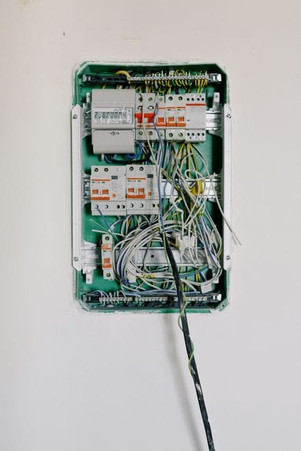
A fuse box diagram is a visual map that shows you exactly which fuse protects which electrical circuit in your vehicle. Think of it as the legend for your car’s electrical center. Each fuse sits in a numbered slot, and the diagram tells you what that slot powers—headlights, radio, power windows, or the fuel pump. Without it, you’re guessing which fuse to pull, and guessing can cost you time or, worse, send you chasing a problem that isn’t there.
The diagram matters because fuses are your first line of defense in electrical diagnostics. When something stops working, the fuse is usually the cheapest, easiest thing to check. But you can’t check what you can’t identify. The diagram eliminates the guesswork, letting you go straight to the correct slot, verify its amperage rating, and determine whether the fuse is the culprit or if the problem lies deeper in the circuit.
Defining the Fuse Box Diagram vs. a Wiring Diagram
It’s easy to confuse a fuse box diagram with a wiring diagram, but they serve different purposes. A fuse box diagram is a simplified map of the fuse box itself — it shows slot numbers, amperage ratings, and which component each fuse protects. A wiring diagram, by contrast, traces the entire electrical path from the battery through relays, switches, and connectors to the final load (like a headlight or motor). The fuse box diagram tells you where to look; the wiring diagram tells you how the current flows. For most DIY diagnostics, the fuse box diagram is your starting point, while the wiring diagram is reserved for deeper electrical tracing when a fuse keeps blowing or a circuit has an intermittent fault.
The Role of the Diagram in Vehicle Electrical Diagnostics
In practice, the fuse box diagram is the cornerstone of any electrical troubleshooting session. When a component fails, the diagram helps you quickly isolate whether the issue is a blown fuse, a faulty relay, or a wiring problem downstream. It also prevents you from pulling the wrong fuse — which can disable critical systems like airbags or ABS — and helps you identify shared circuits where one fuse protects multiple components. A proper diagnostic workflow always starts with the fuse box diagram: identify the circuit, check the fuse, test the relay, and only then move to wiring continuity checks.
Locating Your Fuse Boxes: Under-Hood, Interior, and Trunk Positions
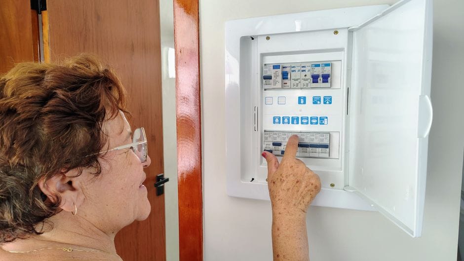
Modern vehicles typically have two or three fuse boxes, each protecting different systems. Knowing where they are — and how to access them — is the first step in using your diagram effectively. The locations are standardized enough that once you know the general pattern, you can find them in almost any car.
Primary Fuse Box (Under-Hood / Engine Bay)
The main fuse box, often called the power distribution center or under-hood fuse box, sits near the battery in the engine bay. It houses high-amperage fuses for heavy-load systems like the starter motor, alternator, radiator fan, and fuel pump. These are typically maxi-fuses or cartridge-type fuses rated from 30A to 120A. The under-hood box also contains most of the vehicle’s relays — the electromechanical switches that control high-current circuits with a low-current signal. Access is usually straightforward: unclip the cover, and the diagram is printed on the underside of the lid or on a sticker adjacent to the box.
Secondary Fuse Box (Interior / Cabin)
The interior fuse box, also called the cabin fuse panel, is typically located under the dashboard on the driver’s side, or occasionally behind a glovebox panel. This box protects lower-amperage circuits for interior systems: power windows, door locks, infotainment, climate control, airbags, and the OBD-II port. These are usually mini or standard blade fuses rated from 5A to 30A. Accessing this box often requires removing a trim panel or lowering the glovebox — check your owner’s manual for the exact procedure, as forcing a panel can crack clips.
Optional Third Fuse Box (Trunk / Rear)
Some vehicles, particularly luxury sedans, SUVs, and cars with rear-mounted batteries, have a third fuse box in the trunk or rear cargo area. This box typically handles rear-seat entertainment, rear climate control, power tailgate, and amplifier circuits. It’s usually located behind a side trim panel or under the trunk floor. The diagram for this box is often printed on a card stored nearby or in the owner’s manual. If your vehicle has a trunk-mounted battery, the main fuse box may also be relocated here.
How to Access Each Box Safely
Detailed Steps Access Each Box Safely
Before opening any fuse box, turn off the ignition and remove the key. For the under-hood box, ensure the engine is cool to avoid burns. Use the clips or screws provided — don’t pry with a metal screwdriver, as you can short terminals. For interior boxes, be gentle with trim panels; they often use plastic clips that break easily. Once open, take a photo of the diagram before removing any fuses — this gives you a reference and helps you remember the original layout. Always use the correct fuse puller tool (usually stored in the fuse box or provided in the vehicle’s tool kit) to avoid damaging the fuse or the socket.
Decoding the Diagram: Symbols, Numbers, and Abbreviations

Once you’ve located your fuse box, the next challenge is reading the diagram itself. Fuse box diagrams use a standardized set of symbols, numbers, and abbreviations that can seem cryptic at first — but once you learn the pattern, you can decode any diagram in minutes.
Understanding Fuse Slot Numbers and Amperage Ratings
Each fuse slot is numbered, and the diagram maps those numbers to the circuits they protect. The amperage rating is critical: it tells you how much current the fuse is designed to handle before it blows. Using a fuse with a higher amperage than specified can melt wiring and start a fire; using a lower one will cause nuisance blowouts. The rating is printed on the fuse itself and color-coded (see the table below). Always replace a fuse with the exact same amperage — never substitute.
Common Abbreviations: ABS
, ECM, IGN, and More
Fuse box diagrams are packed with abbreviations that identify which system each fuse protects. Here are the most common ones you’ll encounter: ABS (Anti-lock Braking System), ECM (Engine Control Module), IGN (Ignition), BCM (Body Control Module), HVAC (Heating, Ventilation, and Air Conditioning), PWR (Power), ACC (Accessory), RAD (Radio), HORN, WIPER, PWR WDW (Power Windows), DRL (Daytime Running Lights), FOG (Fog Lights), and FUEL PUMP. Some diagrams use a numbering system instead of abbreviations — in that case, the legend on the fuse box lid or in the owner’s manual will decode each number. If you see an abbreviation you don’t recognize, consult the owner’s manual; guessing can lead you to the wrong circuit.
Relay Identification and Function
Relays are electromagnetic switches that allow a low-current signal to control a high-current circuit. On the diagram, relays are typically marked with a distinct symbol (often a rectangle with a coil inside) and labeled with abbreviations like FAN RELAY, STARTER RELAY, or FUEL PUMP RELAY. Unlike fuses, relays don’t blow — they fail mechanically or electrically. A clicking sound when you turn the key often indicates the relay is working; silence suggests a failed relay or a lack of control signal. The diagram shows you which relay controls which system, so you can swap a suspect relay with an identical one from a non-critical circuit (like the horn) to test it.
Diagram Symbols and Legend Interpretation
Beyond numbers and abbreviations, fuse box diagrams use symbols to convey information quickly. A solid line typically indicates a direct connection, while a dashed line may indicate a ground or a switched power source. A small circle or dot at a junction means the wires are connected; a crossing without a dot means they pass without connecting. Some diagrams use color coding to match the physical fuse colors. The legend — usually printed on the fuse box cover or in the manual — explains every symbol used. Take a moment to study the legend before diving into troubleshooting; it will save you from misreading the diagram.
Fuse Types and Color-Coded Amperage Reference

Not all fuses are created equal. Understanding the different types and their color codes is essential for correct replacement and safe diagnostics. Using the wrong fuse type or amperage can cause electrical fires or damage sensitive components.
Blade Fuses: Standard, Mini, and Maxi
Blade fuses are the most common type in modern vehicles. They come in three sizes: standard (also called ATO/ATC), mini, and maxi. Standard blade fuses are used for mid-range circuits (10A–30A), mini fuses for lower-amperage circuits (5A–20A) where space is tight, and maxi fuses for high-current circuits (30A–120A) like the alternator or cooling fan. The physical size prevents you from inserting a mini fuse into a maxi slot, but always double-check the diagram to confirm the correct type.
Cartridge and Other Fuse Types
Some vehicles, especially newer models and European brands, use cartridge fuses (also called JCASE or MCASE) or pal-type fuses. Cartridge fuses are rectangular with two metal blades and are used for high-current applications. They don’t have the same color-coding as blade fuses, so you must read the amperage printed on the fuse body. Other rare types include glass tube fuses (found in older vehicles) and resettable circuit breakers (which pop and reset automatically). Always match the exact type specified in your diagram.
Color-Coded Amperage Table for Blade Fuses
Blade fuses follow a standardized color code that makes identification quick. Here’s the reference table:
| Color | Amperage |
|---|---|
| Gray | 2A |
| Violet | 3A |
| Pink | 4A |
| Tan | 5A |
| Brown | 7.5A |
| Red | 10A |
| Blue | 15A |
| Yellow | 20A |
| White/Clear | 25A |
| Green | 30A |
| Orange | 40A (maxi) |
| Red (maxi) | 50A |
| Blue (maxi) | 60A |
| Brown (maxi) | 70A |
| White (maxi) | 80A |
| Violet (maxi) | 100A |
Keep this table handy — it’s your quick reference when a fuse blows and you need to confirm the correct replacement.
How to Read a Fuse Box Diagram Step by Step

Reading a fuse box diagram isn’t difficult once you break it down into a systematic process. Here’s a step-by-step method that works for any vehicle.
Step 1: Identify the Fuse Box and Its Diagram
First, locate the fuse box you need (under-hood, interior, or trunk). The diagram is usually printed on the lid, on a sticker near the box, or in the owner’s manual. If the diagram is missing or faded, search online using your vehicle’s make, model, and year — many manufacturers publish them in PDF form.
Step 2: Find the Circuit You Need
Identify the component that’s not working (e.g., headlights, radio, power windows). Scan the diagram for the corresponding abbreviation or slot number. If the diagram uses numbers only, check the legend to match the number to the component.
Step 3: Check the Amperage Rating
Once you’ve found the slot, note the amperage rating shown on the diagram. This tells you what fuse to look for. Cross-reference with the color code table above to know what color fuse you’re expecting.
Step 4: Locate the Physical Fuse
Using the slot number, find the corresponding fuse in the physical box. Use a flashlight if needed — slots can be tight and poorly lit. Pull the fuse with the plastic fuse puller tool.
Step 5: Inspect and Test the Fuse
Look at the metal strip inside the fuse. If it’s broken or melted, the fuse is blown. For a more reliable test, use a multimeter in continuity mode — a blown fuse will show no continuity. You can also test voltage across the fuse terminals with the ignition on; you should see battery voltage on both sides if the fuse is good.
Step 6: Replace and Verify
Step 6: Details
If the fuse is blown, replace it with the exact same amperage and type. Reinstall the fuse, test the component, and if it works, you’re done. If it blows again immediately, you have a short circuit or an overloaded circuit — proceed to the troubleshooting section below.
Troubleshooting Common Fuse and Relay Issues

Even with a perfect diagram in hand, electrical problems can still be stubborn. Understanding the common failure modes — and how to diagnose them — separates a novice from someone who can confidently handle 80% of electrical faults. Here’s how to approach the most frequent issues.
Why Fuses Blow: Common Causes and Failure Modes
A fuse blows for one of three reasons: a short circuit (wire touching ground), an overloaded circuit (too many accessories drawing power), or a faulty component (a motor seizing and drawing excessive current). A single blown fuse after years of service is often just age or a momentary spike. But if the same fuse blows repeatedly, you have a systemic problem. Check for chafed wires near the fuse box, corroded connectors, or aftermarket accessories that may have been wired into the circuit incorrectly.
How to Test a Fuse with a Multimeter
Visual inspection isn’t always reliable — a fuse can crack internally without visible damage. Use a multimeter set to continuity mode. Touch one probe to each metal terminal of the fuse (remove it from the box first). A beep or near-zero resistance means the fuse is good. Alternatively, set the multimeter to DC voltage, turn the ignition on, and probe the two small test points on top of the fuse (if accessible). You should read battery voltage on both sides. If you have voltage on one side but not the other, the fuse is blown.
Diagnosing a Blown Fuse That Keeps Recurring
If a fuse blows immediately after replacement, don’t just keep swapping fuses — you’ll risk damaging the wiring. First, disconnect the component that the fuse protects. Replace the fuse. If it holds, the component is the culprit. If it blows again with the component disconnected, the short is in the wiring harness. Inspect the harness for pinched, melted, or chafed wires, especially where it passes through metal grommets or near hot engine parts. A wiring diagram (not just the fuse box diagram) is essential for tracing the full circuit path.
Identifying Parasitic Draws
A parasitic draw is a battery drain that occurs when the ignition is off — something is staying powered when it shouldn’t. To test, set your multimeter to DC amps (10A range) and connect it in series between the negative battery terminal and the negative battery cable. With everything off and doors closed, a normal draw is under 50 milliamps. If you see a higher reading, start pulling fuses one by one (using your fuse box diagram to track which circuit you’re disconnecting) until the draw drops. The circuit that causes the drop is the one with the parasitic load.
Relay Failure: Symptoms and Testing
Relays fail in two ways: the coil burns out (no click, no switching) or the contacts weld shut (circuit stays on). Symptoms include a component that won’t turn on, a component that won’t turn off, or intermittent operation. To test a relay, locate it on the diagram, pull it out, and use a multimeter to check coil resistance (typically 50–200 ohms). Apply 12V to the coil terminals and listen for a click while checking continuity across the switch terminals. If the relay clicks but doesn’t pass current, the contacts are burned. Swap with an identical relay from a non-critical circuit to confirm.
Using the Diagram to Trace Short Circuits
When you have a short circuit, the fuse box diagram helps you narrow down which section of the wiring harness to inspect. The diagram shows which components share a fuse — if the fuse protects multiple items, disconnect them all, then reconnect one at a time while monitoring the fuse. When the fuse blows, you’ve found the faulty branch. From there, visually inspect that branch’s wiring for damage. This systematic elimination method is far faster than randomly probing wires.
Real-World Fuse Box Layouts: Popular Models 2015–2025

To bring the theory into practice, let’s look at real-world fuse box layouts from popular vehicles. These examples show how the principles we’ve covered apply to actual cars you might own or work on.
Ford F-150 (2015–2020) Under-Hood Fuse Box
The F-150’s power distribution box is located in the engine bay near the battery. It uses a mix of maxi and mini fuses. Key circuits include: Fuse 1 (40A maxi) for the trailer brake controller, Fuse 15 (20A mini) for the fuel pump, and Fuse 27 (30A mini) for the wiper motor. The diagram is printed on the underside of the cover. A common issue is Fuse 27 blowing due to a faulty wiper motor — the diagram helps you identify it in seconds.
Honda Civic (2016–2021) Interior Fuse Box
The Civic’s interior fuse box is located under the dashboard on the driver’s side, behind a small access panel. It uses mini fuses. Key circuits include: Fuse 1 (10A) for the airbag system, Fuse 13 (20A) for the power windows, and Fuse 22 (7.5A) for the audio system. The diagram is on the back of the access panel. A frequent issue is Fuse 13 blowing when the window motor struggles — the diagram makes it easy to check.
Toyota RAV4 (2019–2024) Engine Bay and Interior Boxes
The RAV4 has two main fuse boxes. The engine bay box (near the battery) handles high-current circuits: Fuse 1 (80A maxi) for the main power, Fuse 5 (30A) for the cooling fan, and Fuse 10 (15A) for the horn. The interior box (behind the glovebox) handles lower-current circuits: Fuse 3 (10A) for the airbag, Fuse 9 (20A) for the rear wiper, and Fuse 15 (7.5A) for the instrument cluster. The diagrams are printed on both covers.
Chevrolet Silverado (2020–2025) Trunk-Mounted Accessory Box
Some Silverado trims have a third fuse box in the rear passenger side cargo area. This box handles trailer lighting, rear entertainment, and the power tailgate. Fuse 2 (30A) controls the power tailgate, Fuse 7 (15A) controls the trailer brake, and Fuse 12 (10A) controls the rear camera. The diagram is on a card stored in the box itself. This is a great example of why you should always check for a third fuse box in larger vehicles.
Fuse Box Diagram vs. Owner’s Manual vs. Online Resources

Where should you get your fuse box diagram? You have several options, each with pros and cons. Knowing which to use in which situation saves time and prevents errors.
When to Trust the Owner’s Manual
The owner’s manual is the authoritative source for your specific vehicle. It contains the official fuse box diagrams, including slot numbers, amperage ratings, and circuit descriptions. It also includes the location of every fuse box and how to access them. Always start here — it’s accurate, model-specific, and free. The downside is that it can be vague for complex circuits, and it may not cover optional equipment or aftermarket additions.
Using Online Fuse Box Diagram Databases
Online resources like fuse-box.info, carmanualshub, and manufacturer websites offer searchable diagrams for virtually every make and model. These are invaluable when you’ve lost your manual or the diagram on the fuse box lid is faded. However, verify the year and trim level carefully — a diagram for a 2019 model may differ from a 2021 model even if the body style looks identical. Cross-reference with the physical fuse box layout before pulling any fuses.
When to Consult a Wiring Diagram Instead
If you’re dealing with a short circuit, intermittent fault, or a problem that persists after replacing fuses and relays, you need a full wiring diagram, not just a fuse box diagram. Wiring diagrams show every wire, connector, and ground point in the circuit. These are available in factory service manuals (often sold as digital downloads) or through subscription services like ALLDATA or Mitchell1. For a DIYer, a wiring diagram is the next step up when the fuse box diagram has taken you as far as it can.
Safety Precautions and When to Call a Professional


Working with your vehicle’s electrical system carries real risks — from electrical shock to fire hazards. Following basic safety protocols keeps you safe and prevents damage to your car’s sensitive electronics.
Essential Safety Rules for Fuse Box Work
Always disconnect the negative battery terminal before working on any fuse box, especially the under-hood unit. This prevents accidental shorts and protects the vehicle’s computer modules from voltage spikes. Wear insulated gloves and safety glasses. Never use metal tools to pry fuses — use the plastic fuse puller. Keep flammable materials away from the engine bay, and never work on electrical components in wet conditions. If you smell burning plastic or see smoke, stop immediately and disconnect the battery.
Signs You Should Stop and Call an Auto Electrician
Some electrical problems are beyond the scope of DIY repair. Call a professional if: you’ve replaced the same fuse three or more times and it keeps blowing; you see melted wiring, burn marks, or a burning smell; the problem involves the airbag system, ABS, or other safety-critical components; you don’t have the proper tools (like a multimeter or wiring diagram); or you’re uncomfortable working with high-voltage systems in hybrid or electric vehicles. A professional has specialized diagnostic equipment that can pinpoint faults in minutes — saving you time and preventing further damage.
How to Avoid Common DIY Mistakes
Detailed Steps Avoid Common DIY Mistakes
The most common mistakes DIYers make include: using a higher-amperage fuse than specified (fire hazard), forcing a fuse into the wrong slot (damaging contacts), overtightening fuse box cover screws (cracking the housing), and ignoring the relay when the fuse is fine. Always double-check the diagram before pulling or inserting anything. Take photos before disconnecting anything. And never work on the electrical system with the engine running unless the diagnostic procedure specifically requires it.
Advanced Diagnostics: Using OBD-II and Multimeters

Once you’ve mastered the fuse box diagram, you can combine it with other diagnostic tools to solve even the most stubborn electrical issues. The OBD-II port and a quality multimeter are your best allies.
Combining Fuse Box Diagrams with OBD-II Codes
When a check engine light or warning message appears, the OBD-II system stores diagnostic trouble codes (DTCs). These codes often point to a specific circuit — for example, a P0685 code indicates an ECM/PCM power relay control circuit malfunction. Your fuse box diagram helps you locate that relay and its associated fuse, allowing you to check power and ground at the relay socket. This combination of code reading and fuse box mapping is the professional approach to diagnostics.
Using a Multimeter for Voltage, Continuity, and Current Tests
A multimeter is essential for verifying what the fuse box diagram tells you. Set it to DC voltage to check that power is reaching the fuse (both sides should read battery voltage with the ignition on). Use continuity mode to test fuses and relays out of the box. Use the amp clamp or series current mode to measure parasitic draws. Always start at the fuse box — the diagram tells you where to probe, and the multimeter tells you what’s actually happening. This two-step process eliminates guesswork.
Interpreting Voltage Drop and Ground Issues
A fuse that tests fine but still doesn’t deliver power to a component often indicates a voltage drop — resistance in the circuit that reduces available voltage. Use your multimeter to measure voltage at the component’s connector while it’s under load. If you see significantly less than battery voltage, there’s resistance somewhere between the fuse and the component. Check the ground side too — a poor ground can cause the same symptoms as a blown fuse. The fuse box diagram helps you trace the power path, but you’ll need a wiring diagram to trace the ground path.
Frequently Asked Questions

What does a blown fuse look like?
A blown blade fuse typically has a visibly broken or melted metal strip inside the clear plastic housing. You may also see a dark smudge or discoloration on the plastic. However, some fuses fail internally without visible damage — always test with a multimeter for certainty.
Can I use a higher amperage fuse temporarily?
No. Never replace a fuse with a higher amperage rating, even temporarily. The fuse is sized to protect the wiring — a higher-rated fuse allows excessive current to flow, which can melt wires and start a fire. If you don’t have the correct fuse, wait until you can get one.
Why does my fuse keep blowing?
Recurring fuse blowouts indicate a short circuit, an overloaded circuit, or a failing component. Check for chafed wires, corroded connectors, or aftermarket accessories wired incorrectly. If you can’t find the cause, consult a professional.
Where can I find a fuse box diagram for my specific car?
Check the fuse box cover (the diagram is often printed on the underside), your owner’s manual, or online databases like fuse-box.info. For the most accurate information, use the manufacturer’s official resources or a factory service manual.
What’s the difference between a fuse and a relay?
A fuse protects a circuit by breaking the connection when current exceeds a safe level. A relay is a switch that uses a low-current signal to control a high-current circuit. Fuses blow; relays click and switch. Both are shown on the fuse box diagram, but they serve different functions.
Is it safe to work on my fuse box without disconnecting the battery?
It’s safer to disconnect the negative battery terminal first. This prevents accidental shorts and protects sensitive electronics. For simple fuse inspections, you can often work with the battery connected, but for any removal or replacement work, disconnect it.
Conclusion: Master Your Vehicle’s Electrical Center

Your fuse box diagram is more than a piece of paper — it’s the roadmap to your vehicle’s entire electrical system. With the knowledge from this guide, you can locate any fuse box, decode any diagram, identify the correct fuse or relay, and troubleshoot common electrical faults with confidence. You’ve learned the difference between fuse box diagrams and wiring diagrams, the meaning of common abbreviations, the color-coded amperage system, and the step-by-step process for reading and using these diagrams effectively.
You now know how to test fuses with a multimeter, diagnose recurring blowouts, identify parasitic draws, and recognize when a problem is beyond your skill level. You’ve seen real-world examples from popular vehicles and learned where to find reliable diagrams when you need them. Most importantly, you understand the safety precautions that keep you and your vehicle protected.
Electrical diagnostics doesn’t have to be intimidating. Start with the fuse box diagram, work through the steps methodically, and you’ll resolve the majority of common electrical issues yourself. For the rest, you’ll know exactly when to call a professional — and you’ll be able to describe the problem accurately, saving time and money. Pop the hood, grab your diagram, and take control of your vehicle’s electrical health.