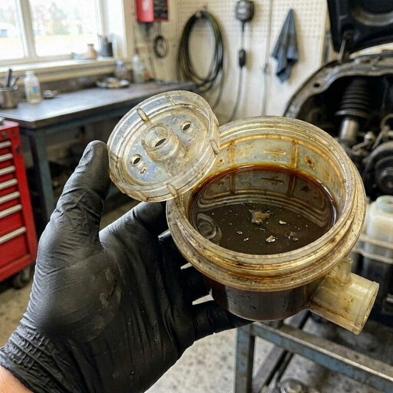
Bellhousing Alignment: Complete Guide
Bellhousing Alignment: The Complete Guide to Preventing Transmission Failure
Bellhousing alignment is the precise geometric relationship between the engine’s crankshaft centerline and the transmission’s input shaft centerline. It is not a “set it and forget it” spec. It is a measurable, adjustable dimension that determines whether your drivetrain survives or destroys itself. When these two axes deviate beyond factory tolerance, you get a cascade of failures. These include premature bearing wear, input shaft seal leakage, clutch chatter, and in severe cases, cracked transmission cases. This guide covers the complete measurement process, correction methods, and the tools required to get it right the first time.
We’ll break down the five critical attributes of proper bellhousing alignment. These are runout (total indicated runout, or TIR), bore concentricity, face squareness, dowel pin fitment, and the often-overlooked effect of engine plate thickness. You’ll learn why a dial indicator is your best friend. You’ll learn how to interpret offset versus angular misalignment. You’ll learn when offset dowel pins are the right fix versus when you need a machine shop. We’ll also cover the specific challenges of popular platforms. These include GM LS swaps, Ford 302 builds, and Mopar 904/727 transmissions. Each has its own quirks and tolerance requirements.
What makes this guide different is the data. Most articles tell you “check your runout” without explaining what good looks like. We’re giving you the actual factory tolerance tables from major manufacturers. We’re giving you a step-by-step measurement protocol with torque specs. We’re also giving you honest limitations of DIY correction methods. If you’re chasing a vibration that only appears under load, this is the definitive resource. If you’ve already toasted one input shaft bearing, this is the definitive resource. It will help you diagnose and fix the root cause, not the symptom.
What Is Bellhousing Alignment and Why It Determines Your Transmission’s Lifespan
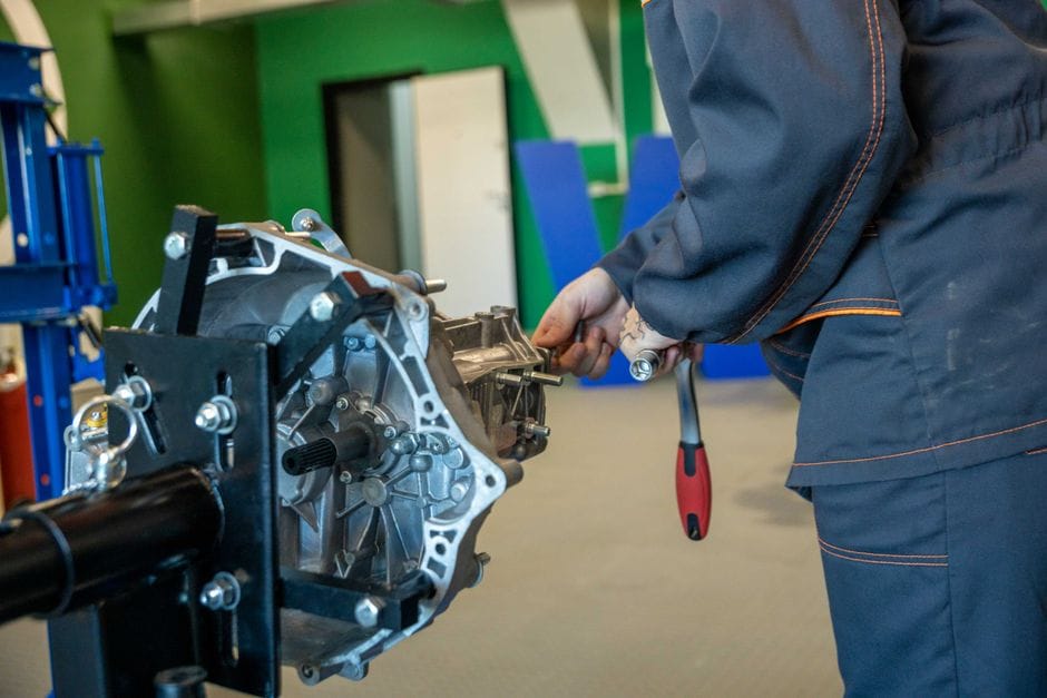
Bellhousing alignment is the measurement of how perfectly the transmission input shaft’s centerline matches the crankshaft centerline. When these two rotating axes line up within factory tolerance, the drivetrain runs smoothly. When they don’t, you get premature bearing wear, gear noise, and eventually catastrophic transmission failure.
The bellhousing is the aluminum or cast-iron component that bolts the transmission to the engine block. It does more than physically connect two parts. It establishes the geometric relationship between the engine’s output and the gearbox’s input. Get that relationship wrong by a few thousandths of an inch, and the input shaft bearing becomes the sacrificial lamb.
Defining the Entity: Concentricity vs. Parallelism
Concentricity refers to how well the centerline of the transmission input shaft aligns with the centerline of the crankshaft. These two axes should share the same rotational center. Parallelism, on the other hand, refers to how square the transmission face is relative to the engine block’s rear face. A bellhousing can be perfectly parallel but off-center. It can also be perfectly centered but tilted. Both conditions cause distinct failure modes. Concentricity errors manifest as radial loading on the input shaft bearing. Parallelism errors cause thrust loading and clutch engagement problems.
How Bellhousing Alignment Differs from Engine/Transmission Mount Alignment
Engine and transmission mounts position the powertrain in the chassis. They control fore-aft tilt and side-to-side positioning relative to the vehicle’s frame. Bellhousing alignment is entirely different. It is about the internal geometric relationship between two rotating components. You can have perfectly good motor mounts and still have catastrophic bellhousing misalignment. Conversely, worn mounts don’t cause bellhousing runout. They cause drivetrain angle issues that manifest as vibration under acceleration. They won’t destroy the input shaft bearing the way bellhousing misalignment does.
The Physics: What Happens When the Centerlines Don’t Match
When the crankshaft centerline and input shaft centerline deviate, the input shaft is forced to rotate around an eccentric path. This creates a cyclic radial force on the input shaft bearing at engine speed. At 3,000 RPM, that’s 50 cycles per second of hammering on the bearing. The bearing’s rollers or balls are designed for pure radial load. They are not designed for this oscillating eccentric load. The result is brinelling, spalling, and eventual catastrophic failure. The same eccentricity also causes the clutch disc to engage and release unevenly. This produces chatter and premature friction material wear.
The 4 Critical Symptoms of Misaligned Bellhousing (And How to Diagnose Them)

Premature Input Shaft Bearing Wear
The most common symptom of bellhousing misalignment is accelerated wear on the transmission’s input shaft bearing. This bearing supports the input shaft at the front of the gearbox. When the bellhousing is misaligned, the input shaft is forced into a slight orbit rather than a pure rotation. The bearing’s rolling elements are subjected to cyclic side loads they were never designed to handle. You’ll typically notice this as a whine or rumble that increases with engine speed, even in neutral. If you catch it early, you might save the bearing. If not, the bearing race will score. Metal particles will circulate through the transmission, destroying synchronizers and gear teeth.
Clutch Chatter and Release Issues
Clutch chatter — that violent shudder when engaging from a stop — is often misdiagnosed as a worn clutch disc or pressure plate. But a misaligned bellhousing causes the clutch disc to engage unevenly. The disc’s friction surface contacts the flywheel and pressure plate in a rocking motion rather than a flat, even clamp. This produces a grab-and-release cycle that feels like chatter. Release issues manifest as a pedal that feels inconsistent or a clutch that drags when disengaged. The input shaft’s eccentric orbit prevents the disc from fully releasing from the flywheel. This causes gear grinding during shifts.
Torque Converter Shudder
In automatic transmissions, bellhousing misalignment causes torque converter shudder — a vibration felt during light throttle cruise or torque converter lockup. The converter’s pump and turbine are forced to operate with an eccentric input shaft, creating hydraulic imbalance. This shows up as a subtle vibration that’s most noticeable at highway speeds when the converter locks. It’s often mistaken for a driveline vibration or a failing converter clutch. But the root cause is the input shaft’s orbit, not the converter itself. Replacing the converter without fixing the alignment is a wasted expense.
Transmission Case Cracking and Seal Failure
In severe cases, misalignment causes the transmission case to crack at the bellhousing mounting flange. The cyclic loading from the eccentric input shaft fatigues the aluminum case over time. Input shaft seal failure is another common symptom — the seal lip is designed to run on a concentric shaft, and an eccentric shaft wears an oval pattern into the seal, causing leaks. These symptoms are the end-stage of misalignment, and by the time they appear, internal damage is already extensive.
How to Measure Bellhousing Runout: Step-by-Step Dial Indicator Protocol

Tools Required for Accurate Measurement
You need a dial indicator with 0.001-inch (0.025 mm) resolution, a magnetic base, a rigid extension arm, and a way to rotate the crankshaft. A degree wheel or timing tape on the harmonic balancer helps you take consistent readings at 90-degree intervals. You’ll also need a straightedge and feeler gauges to check the bellhousing face for flatness. For the bore measurement, you need an inside micrometer or a bore gauge. Some professionals use a dial bore gauge, but a telescoping gauge with a micrometer works fine for DIY use.
Step 1: Mounting the Dial Indicator for Bore Runout
Remove the transmission and clutch assembly. Mount the dial indicator to the flywheel or a fixture bolted to the crankshaft flange. Position the indicator tip against the inside of the bellhousing bore where the transmission input shaft passes through. Zero the indicator, then rotate the crankshaft 90 degrees and record the reading. Continue at 180, 270, and 360 degrees. The difference between the highest and lowest readings is the total indicated runout (TIR). Factory tolerance for most applications is 0.005 inches TIR or less, though some high-performance applications require 0.003 inches or better.
Step 2: Measuring Face Squareness (Parallelism)
With the same dial indicator setup, reposition the indicator tip to contact the flat face of the bellhousing where the transmission bolts up. Rotate the cranks
shaft through 360 degrees, recording readings at each 90-degree interval. The difference between maximum and minimum readings on the face indicates parallelism error. This measurement tells you if the bellhousing face is tilted relative to the crankshaft centerline. Most factory specifications call for 0.004 inches TIR or less on face squareness. If you find excessive face runout, the bellhousing mounting surface may need machining or shimming.
Step 3: Interpreting the Readings — Offset vs. Angular Misalignment
Bore runout readings indicate offset misalignment — the input shaft centerline is displaced laterally from the crankshaft centerline. Face runout readings indicate angular misalignment — the transmission is tilted relative to the engine. A bellhousing can have both conditions simultaneously. To isolate which correction method to use, compare your readings against the factory tolerance table. If bore runout exceeds spec but face runout is within spec, you need offset dowel pins. If face runout exceeds spec, you need to machine the bellhousing face or use shims. If both are out of spec, you need a combination of corrections.
Step 4: Documenting Readings and Establishing a Baseline
Always record your readings in a log with the crankshaft position noted for each measurement. This allows you to verify your corrections after installing offset dowel pins or machining. A common mistake is taking only one set of readings and assuming they’re accurate. Always repeat the measurement twice to confirm consistency. If readings vary by more than 0.001 inches between runs, your indicator setup is unstable — check the magnetic base and extension arm rigidity before proceeding.
Factory Tolerance Tables: What the Manufacturers Actually Specify

GM LS and Small-Block Tolerances
General Motors specifies a maximum of 0.005 inches TIR for bore runout and 0.004 inches for face squareness on LS engines and traditional small-blocks. However, GM performance documentation recommends 0.003 inches TIR for high-RPM applications and racing use. The factory dowel pins on GM engines are notoriously soft and often deform during installation, which is why aftermarket offset dowel pins are a common upgrade even on stock builds.
Ford Windsor and Modular Tolerances
Ford specifies 0.005 inches TIR for bore runout on Windsor small-blocks and 0.006 inches on Modular engines. Face squareness tolerance is 0.004 inches for both families. Ford’s factory dowel pins are more solid than GM’s, but the bellhousing mounting surface on many aftermarket bellhousings requires verification. The 302 and 351W platforms are particularly sensitive to bellhousing thickness variations, which affect input shaft engagement depth.
Mopar 904/727 and Gen III Hemi Tolerances
Chrysler specifies 0.005 inches TIR for bore runout on the TorqueFlite 904 and 727 transmissions. Face squareness tolerance is 0.005 inches. The Gen III Hemi platform uses a different bellhousing pattern and specifies 0.004 inches TIR for bore runout. Mopar bellhousings are known for casting shift, so always verify alignment even on factory parts. The 904/727 family is particularly sensitive to input shaft bearing failure when alignment is neglected.
European and Asian Platform Considerations
BMW, Mercedes, and Toyota specify tighter tolerances — typically 0.003 inches TIR for bore runout and 0.002 inches for face squareness. These platforms use precision-machined bellhousings and often have alignment dowels integrated into the engine block. Aftermarket bellhousings for these platforms require careful verification because manufacturing tolerances vary significantly between brands. Always check the manufacturer’s service manual for the exact specification for your specific engine and transmission combination.
How to Fix Bellhousing Misalignment: Offset Dowel Pins, Shims, and Machining

Offset Dowel Pins: The Primary Correction Method
Offset dowel pins are the most common solution for bore runout correction. These pins have an eccentric offset — typically 0.007, 0.014, or 0.021 inches — that allows you to shift the bellhousing relative to the engine block. Install the pins, rotate them to the correct orientation, and re-measure. The process is iterative: install, measure, adjust, re-measure. Most applications require two to three iterations to achieve zero runout. Quality offset dowel pins are hardened steel and use a hex socket for adjustment. Avoid cheap pins that deform during installation.
Shimming for Face Squareness Correction
When face runout exceeds specification, shims placed between the bellhousing and engine block can correct angular misalignment. Shims are available in thicknesses from 0.001 to 0.010 inches. Place shims at the low side of the face runout reading to bring the face square. This method requires careful measurement and multiple iterations. A common mistake is using too many shims, which can cause bolt interference or stress concentration. Always use hardened shims designed for this purpose — soft aluminum shims will crush and compromise the correction.
Machining the Bellhousing Face
For severe face misalignment or bellhousings with casting shift, machining is the definitive fix. A machine shop can cut the bellhousing mounting face square to the bore centerline. This requires a large lathe or a specialized bellhousing fixture. The cost is typically $100 to $200, which is reasonable compared to the cost of a transmission rebuild. After machining, verify the bellhousing thickness to ensure the transmission input shaft still engages correctly with the clutch or torque converter.
When to Replace the Bellhousing Instead of Correcting
If the bellhousing has cracks, excessive wear in the dowel pin holes, or has been previously machined beyond specification, replacement is the better option. Aftermarket bellhousings from manufacturers like Quick Time, Lakewood, and McLeod are precision-machined and often come with alignment verification documentation. These are particularly popular for engine swap applications where factory bellhousings may not fit or may have unknown alignment characteristics.
Platform-Specific Challenges: LS Swaps, Ford 302 Builds, and Mopar Transmissions

GM LS Swap Bellhousing Alignment
LS swaps are the most common engine swap platform, and bellhousing alignment is frequently overlooked. The LS engine block has dowel pins that are often removed or damaged during the swap process. Aftermarket bellhousings for LS swaps vary significantly in quality. The transmission choice — whether T56, 4L60E, or 4L80E — affects the bellhousing pattern and input shaft length. Always verify alignment on LS swaps, especially when using adapter plates, because the adapter adds another variable to the geometric equation.
Ford 302 and 351W Bellhousing Considerations
The Ford small-block family has a unique bellhousing bolt pattern that’s shared across many generations. However, the crankshaft flange thickness varies between 28-ounce and 50-ounce imbalance flywheels, which affects input shaft engagement. Aftermarket bellhousings for Ford small-blocks are common, but quality varies. The factory bellhousing on Fox-body Mustangs is known for casting shift, so verification is essential. The 351W has a taller deck height, which changes the bellhousing-to-block relationship.
Mopar 904/727 and Gen III Hemi Specifics
Mopar A-body and B-body bellhousings are known for casting shift, making alignment verification critical. The 904 and 727 transmissions share the same bellhousing pattern, but input shaft lengths differ. Gen III Hemi swaps into older Mopars require adapter plates, which introduce additional alignment variables. The Hemi’s factory bellhousing is precision-machined, but aftermarket adapters often require offset dowel pins to achieve proper alignment.
Adapter Plates and Their Impact on Alignment
Adapter plates are common in engine swaps, but they add thickness and potential misalignment. Every adapter plate should be checked for flatness and parallelism before installation. A warped adapter plate will introduce face runout that’s difficult to diagnose. When using an adapter plate, always measure alignment with the plate installed, not just the bellhousing alone. The plate’s bolt holes can also be off-center, introducing bore runout that requires offset dowel pins to correct.
Torque Converter and Clutch Engagement: How Alignment Affects Engagement
Torque Converter and Clutch Engagement: How Alignment Affects Engagement

How Misalignment Affects Clutch Disc Engagement
When the bellhousing is misaligned, the clutch disc is forced to engage at an angle relative to the flywheel and pressure plate. This causes the disc to make initial contact on one side before the other, creating a rocking motion during engagement. The result is uneven wear on the friction material, hot spots on the flywheel, and the characteristic chatter that drivers feel when launching from a stop. Over time, this uneven engagement also fatigues the pressure plate diaphragm fingers, leading to premature pressure plate failure.
Torque Converter Pilot and Stator Alignment
In automatic transmissions, the torque converter’s pilot hub must center perfectly in the crankshaft’s pilot bore. Bellhousing misalignment forces the converter to run eccentric, which causes the pump drive hub to wear unevenly. The stator shaft — which is splined to the transmission case — also experiences abnormal loading. This manifests as torque converter shudder during lockup and premature pump bushing wear. The converter’s internal thrust washers are particularly vulnerable, as eccentric operation creates axial loading they weren’t designed to handle.
Input Shaft Spline Wear and Fretting
The clutch disc slides on the input shaft splines. When the bellhousing is misaligned, the disc doesn’t slide straight — it rocks on the splines, causing fretting wear. This appears as a rough, pitted surface on the splines and a disc hub that binds during disengagement. In severe cases, the splines can wear enough to cause the disc to hang up, preventing full clutch release. This is often misdiagnosed as a worn clutch disc, but the root cause is the input shaft’s eccentric orbit.
Flywheel and Flexplate Stress
The flywheel or flexplate is bolted to the crankshaft and must run perfectly true. Bellhousing misalignment doesn’t directly affect the flywheel’s runout, but it does affect how the clutch assembly interacts with it. The pressure plate bolts to the flywheel, and if the transmission input shaft is pushing the clutch disc at an angle, the pressure plate’s clamping force becomes uneven. This creates localized stress on the flywheel surface, leading to heat checking and warpage over time.
Common Mistakes and Myths About Bellhousing Alignment

Myth: “It’s Fine If It Bolts Up”
One of the most dangerous assumptions in drivetrain work is that if the bellhousing bolts to the engine and the transmission bolts to the bellhousing, everything is aligned. Bolts only locate parts in one plane — they don’t guarantee concentricity. A bellhousing can bolt up perfectly and still be off by 0.020 inches or more. The only way to know is to measure. This myth is responsible for countless premature transmission failures.
Myth: “New Parts Are Always In Spec”
Aftermarket bellhousings, even from reputable manufacturers, can have manufacturing tolerances that stack up against your specific engine block. Casting shift, machining errors, and even shipping damage can cause a new bellhousing to be out of spec. Factory bellhousings are not immune either — they’re made to a tolerance, and that tolerance may not be tight enough for your application. Always verify new parts before installation.
Mistake: Not Torquing Bolts Before Measuring
Measuring bellhousing alignment with loose or improperly torqued bolts gives false readings. The bellhousing can shift when bolts are tightened, changing the alignment. Always torque the bellhousing bolts to factory specification — typically 30 to 40 ft-lbs for most applications — before taking any measurements. Also, torque the flywheel or flexplate bolts to spec, as a loose flywheel will cause erratic indicator readings.
Mistake: Ignoring the Pilot Bearing
The pilot bearing in the crankshaft centers the input shaft’s tip. If the pilot bearing is worn or incorrectly installed, it can mask or exacerbate bellhousing misalignment. Always inspect and replace the pilot bearing during any clutch or transmission work. A worn pilot bearing can cause input shaft runout that’s incorrectly attributed to the bellhousing. Conversely, a new pilot bearing in a worn crankshaft bore will also cause issues.
Tools and Kits for Bellhousing Alignment: What You Need and What to Avoid

Dial Indicators and Magnetic Bases
A quality dial indicator with 0.001-inch resolution is essential. Look for indicators with a jeweled movement and a clear, easy-to-read face. The magnetic base must be strong enough to hold the indicator rigidly — a weak base will flex and give false readings. Extension arms should be rigid and lock securely. Avoid cheap combination kits that include flimsy arms and bases, as they introduce measurement error that’s difficult to detect.
Offset Dowel Pin Kits
Offset dowel pin kits come in various offsets — typically 0.007, 0.014, and 0.021 inches. Quality kits include hardened steel pins with hex sockets for adjustment. Some kits include a removal tool for extracting the factory dowel pins. Avoid kits with soft pins that deform during installation. The best kits include a measurement chart to help you calculate the correct pin orientation based on your runout readings.
Bellhousing Alignment Fixtures
Professional alignment fixtures bolt to the crankshaft flange and provide a precise mounting point for the dial indicator. These fixtures eliminate the variability of mounting the indicator to the flywheel or harmonic balancer. They’re more expensive than DIY setups but provide the most accurate and repeatable measurements. For frequent transmission work, a dedicated fixture is worth the investment.
Shim Kits and Machining Services
Shim kits for face squareness correction are available in precision thicknesses. Look for hardened steel shims with a smooth surface finish. For machining services, choose a shop with experience in bellhousing work — they should have a fixture to hold the bellhousing and a lathe large enough to machine the face. Ask for a before-and-after measurement report to verify the work.
Step-by-Step Correction Procedure: From Measurement to Zero Runout

Step 1: Document Your Baseline Readings
Before making any corrections, record your initial bore runout and face runout readings. Note the crankshaft position for each reading. This baseline tells you the magnitude and direction of the misalignment. For bore runout, the high reading indicates the direction the bellhousing needs to move. For face runout, the low reading indicates where shims need to be placed.
Step 2: Remove and Prepare for Correction
Remove the bellhousing from the engine. Clean the mounting surfaces thoroughly — any debris or burrs will affect the correction. Inspect the dowel pin holes for damage or ovaling. If the holes are damaged, they may need to be welded and re-drilled, or the bellhousing may need replacement. Check the engine block’s dowel pin holes for wear as well.
Step 3: Install Offset Dowel Pins
Remove the factory dowel pins using a puller or by threading a bolt into the pin’s internal threads. Install the offset dowel pins with the offset direction marked. Start with the pin offset that’s closest to your measured runout. Install the bellhousing, torque the bolts to spec, and re-measure. Adjust the pin orientation based on the new readings. Repeat until bore runout is within specification.
Step 4: Correct Face Squareness with Shims
If face runout exceeds specification after bore correction, add shims at the low-reading location. Install the shims between the bellhousing and engine block, then re-torque and re-measure. Add or remove shims in small increments until face runout is within spec. Remember that adding shims changes the bellhousing’s position, which can affect bore runout — you may need to iterate between bore and face corrections.
Step 5: Final Verification and Documentation
Step 5: Details
Step 5: Details
After achieving zero or near-zero runout, perform a final measurement and document the results. Torque all bolts to specification and verify that the transmission installs smoothly. Check that the input shaft engages the pilot bearing without binding.
Bellhousing alignment is the precise geometric relationship between the engine’s crankshaft centerline and the transmission’s input shaft centerline. This isn’t a “set it and forget it” spec — it’s a measurable, adjustable dimension that determines whether your drivetrain survives or destroys itself. When these two axes deviate beyond factory tolerance, you get a cascade of failures: premature bearing wear, input shaft seal leakage, clutch chatter, and in severe cases, cracked transmission cases. This guide covers the complete measurement process, correction methods, and the tools required to get it right the first time.
We’ll break down the five critical attributes of proper bellhousing alignment: runout (total indicated runout, or TIR), bore concentricity, face squareness, dowel pin fitment, and the often-overlooked effect of engine plate thickness. You’ll learn why a dial indicator is your best friend, how to interpret offset versus angular misalignment, and when offset dowel pins are the right fix versus when you need a machine shop. We’ll also cover the specific challenges of popular platforms — from GM LS swaps to Ford 302 builds and Mopar 904/727 transmissions — because each has its own quirks and tolerance requirements.
What makes this guide different is the data. Most articles tell you “check your runout” without explaining what good looks like. We’re giving you the actual factory tolerance tables from major manufacturers, a step-by-step measurement protocol with torque specs, and honest limitations of DIY correction methods. If you’re chasing a vibration that only appears under load, or you’ve already toasted one input shaft bearing, this is the definitive resource to diagnose and fix the root cause — not the symptom.
What Is Bellhousing Alignment and Why It Determines Your Transmission’s Lifespan
Bellhousing alignment is the measurement of how perfectly the transmission input shaft’s centerline matches the crankshaft centerline. When these two rotating axes line up within factory tolerance, the drivetrain runs smoothly. When they don’t, you get premature bearing wear, gear noise, and eventually catastrophic transmission failure.
The bellhousing is the aluminum or cast-iron component that bolts the transmission to the engine block. It does more than physically connect two parts. It establishes the geometric relationship between the engine’s output and the gearbox’s input. Get that relationship wrong by a few thousandths of an inch, and the input shaft bearing becomes the sacrificial lamb.
Defining the Entity: Concentricity vs. Parallelism
Concentricity refers to how well the centerline of the transmission input shaft aligns with the centerline of the crankshaft. These two axes should share the same rotational center. Parallelism, on the other hand, refers to how square the transmission face is relative to the engine block’s rear face. A bellhousing can be perfectly parallel but off-center, or perfectly centered but tilted. Both conditions cause distinct failure modes. Concentricity errors manifest as radial loading on the input shaft bearing, while parallelism errors cause thrust loading and clutch engagement problems.
How Bellhousing Alignment Differs from Engine/Transmission Mount Alignment
Engine and transmission mounts position the powertrain in the chassis. They control fore-aft tilt and side-to-side positioning relative to the vehicle’s frame. Bellhousing alignment is entirely different — it’s about the internal geometric relationship between two rotating components. You can have perfectly good motor mounts and still have catastrophic bellhousing misalignment. Conversely, worn mounts don’t cause bellhousing runout; they cause drivetrain angle issues that manifest as vibration under acceleration, but they won’t destroy the input shaft bearing the way bellhousing misalignment does.
The Physics: What Happens When the Centerlines Don’t Match
When the crankshaft centerline and input shaft centerline deviate, the input shaft is forced to rotate around an eccentric path. This creates a cyclic radial force on the input shaft bearing at engine speed. At 3,000 RPM, that’s 50 cycles per second of hammering on the bearing. The bearing’s rollers or balls are designed for pure radial load, not this oscillating eccentric load. The result is brinelling, spalling, and eventual catastrophic failure. The same eccentricity also causes the clutch disc to engage and release unevenly, producing chatter and premature friction material wear.
The 4 Critical Symptoms of Misaligned Bellhousing (And How to Diagnose Them)
Premature Input Shaft Bearing Wear
The most common symptom of bellhousing misalignment is accelerated wear on the transmission’s input shaft bearing. This bearing supports the input shaft at the front of the gearbox. When the bellhousing is misaligned, the input shaft is forced into a slight orbit rather than a pure rotation. The bearing’s rolling elements are subjected to cyclic side loads they were never designed to handle. You’ll typically notice this as a whine or rumble that increases with engine speed, even in neutral. If you catch it early, you might save the bearing. If not, the bearing race will score, and metal particles will circulate through the transmission, destroying synchronizers and gear teeth.
Clutch Chatter and Release Issues
Clutch chatter — that violent shudder when engaging from a stop — is often misdiagnosed as a worn clutch disc or pressure plate. But a misaligned bellhousing causes the clutch disc to engage unevenly. The disc’s friction surface contacts the flywheel and pressure plate in a rocking motion rather than a flat, even clamp. This produces a grab-and-release cycle that feels like chatter. Release issues manifest as a pedal that feels inconsistent or a clutch that drags when disengaged. The input shaft’s eccentric orbit prevents the disc from fully releasing from the flywheel, causing gear grinding during shifts.
Torque Converter Shudder
In automatic transmissions, bellhousing misalignment causes torque converter shudder — a vibration felt during light throttle cruise or torque converter lockup. The converter’s pump and turbine are forced to operate with an eccentric input shaft, creating hydraulic imbalance. This shows up as a subtle vibration that’s most noticeable at highway speeds when the converter locks. It’s often mistaken for a driveline vibration or a failing converter clutch. But the root cause is the input shaft’s orbit, not the converter itself. Replacing the converter without fixing the alignment is a wasted expense.
Transmission Case Cracking and Seal Failure
In severe cases, misalignment causes the transmission case to crack at the bellhousing mounting flange. The cyclic loading from the eccentric input shaft fatigues the aluminum case over time. Input shaft seal failure is another common symptom — the seal lip is designed to run on a concentric shaft, and an eccentric shaft wears an oval pattern into the seal, causing leaks. These symptoms are the end-stage of misalignment, and by the time they appear, internal damage is already extensive.
How to Measure Bellhousing Runout: Step-by-Step Dial Indicator Protocol
Tools Required for Accurate Measurement
You need a dial indicator with 0.001-inch (0.025 mm) resolution, a magnetic base, a rigid extension arm, and a way to rotate the crankshaft. A degree wheel or timing tape on the harmonic balancer helps you take consistent readings at 90-degree intervals. You’ll also need a straightedge and feeler gauges to check the bellhousing face for flatness. For the bore measurement, you need an inside micrometer or a bore gauge. Some professionals use a dial bore gauge, but a telescoping gauge with a micrometer works fine for DIY use.
Step 1: Mounting the Dial Indicator for Bore Runout
Remove the transmission and clutch assembly. Mount the dial indicator to the flywheel or a fixture bolted to the crankshaft flange. Position the indicator tip against the inside of the bellhousing bore where the transmission input shaft passes through. Zero the indicator, then rotate the crankshaft 90 degrees and record the reading. Continue at 180, 270, and 360 degrees. The difference between the highest and lowest readings is the total indicated runout (TIR). Factory tolerance for most applications is 0.005 inches TIR or less, though some high-performance applications require 0.003 inches or better.
Step 2: Measuring Face Squareness (Parallelism)
With the same dial indicator setup, reposition the indicator tip to contact the flat face of the bellhousing where the transmission bolts up. Rotate the cranks
shaft through 360 degrees, recording readings at each 90-degree interval. The difference between maximum and minimum readings on the face indicates parallelism error. This measurement tells you if the bellhousing face is tilted relative to the crankshaft centerline. Most factory specifications call for 0.004 inches TIR or less on face squareness. If you find excessive face runout, the bellhousing mounting surface may need machining or shimming.
Step 3: Interpreting the Readings — Offset vs. Angular Misalignment
Bore runout readings indicate offset misalignment — the input shaft centerline is displaced laterally from the crankshaft centerline. Face runout readings indicate angular misalignment — the transmission is tilted relative to the engine. A bellhousing can have both conditions simultaneously. To isolate which correction method to use, compare your readings against the factory tolerance table. If bore runout exceeds spec but face runout is within spec, you need offset dowel pins. If face runout exceeds spec, you need to machine the bellhousing face or use shims. If both are out of spec, you need a combination of corrections.
Step 4: Documenting Readings and Establishing a Baseline
Always record your readings in a log with the crankshaft position noted for each measurement. This allows you to verify your corrections after installing offset dowel pins or machining. A common mistake is taking only one set of readings and assuming they’re accurate. Always repeat the measurement twice to confirm consistency. If readings vary by more than 0.001 inches between runs, your indicator setup is unstable — check the magnetic base and extension arm rigidity before proceeding.
Factory Tolerance Tables: What the Manufacturers Actually Specify
GM LS and Small-Block Tolerances
General Motors specifies a maximum of 0.005 inches TIR for bore runout and 0.004 inches for face squareness on LS engines and traditional small-blocks. However, GM performance documentation recommends 0.003 inches TIR for high-RPM applications and racing use. The factory dowel pins on GM engines are notoriously soft and often deform during installation, which is why aftermarket offset dowel pins are a common upgrade even on stock builds.
Ford Windsor and Modular Tolerances
Ford specifies 0.005 inches TIR for bore runout on Windsor small-blocks and 0.006 inches on Modular engines. Face squareness tolerance is 0.004 inches for both families. Ford’s factory dowel pins are more solid than GM’s, but the bellhousing mounting surface on many aftermarket bellhousings requires verification. The 302 and 351W platforms are particularly sensitive to bellhousing thickness variations, which affect input shaft engagement depth.
Mopar 904/727 and Gen III Hemi Tolerances
Chrysler specifies 0.005 inches TIR for bore runout on the TorqueFlite 904 and 727 transmissions. Face squareness tolerance is 0.005 inches. The Gen III Hemi platform uses a different bellhousing pattern and specifies 0.004 inches TIR for bore runout. Mopar bellhousings are known for casting shift, so always verify alignment even on factory parts. The 904/727 family is particularly sensitive to input shaft bearing failure when alignment is neglected.
European and Asian Platform Considerations
BMW, Mercedes, and Toyota specify tighter tolerances — typically 0.003 inches TIR for bore runout and 0.002 inches for face squareness. These platforms use precision-machined bellhousings and often have alignment dowels integrated into the engine block. Aftermarket bellhousings for these platforms require careful verification because manufacturing tolerances vary significantly between brands. Always check the manufacturer’s service manual for the exact specification for your specific engine and transmission combination.
How to Fix Bellhousing Misalignment: Offset Dowel Pins, Shims, and Machining
Offset Dowel Pins: The Primary Correction Method
Offset dowel pins are the most common solution for bore runout correction. These pins have an eccentric offset — typically 0.007, 0.014, or 0.021 inches — that allows you to shift the bellhousing relative to the engine block. Install the pins, rotate them to the correct orientation, and re-measure. The process is iterative: install, measure, adjust, re-measure. Most applications require two to three iterations to achieve zero runout. Quality offset dowel pins are hardened steel and use a hex socket for adjustment. Avoid cheap pins that deform during installation.
Shimming for Face Squareness Correction
When face runout exceeds specification, shims placed between the bellhousing and engine block can correct angular misalignment. Shims are available in thicknesses from 0.001 to 0.010 inches. Place shims at the low side of the face runout reading to bring the face square. This method requires careful measurement and multiple iterations. A common mistake is using too many shims, which can cause bolt interference or stress concentration. Always use hardened shims designed for this purpose — soft aluminum shims will crush and compromise the correction.
Machining the Bellhousing Face
For severe face misalignment or bellhousings with casting shift, machining is the definitive fix. A machine shop can cut the bellhousing mounting face square to the bore centerline. This requires a large lathe or a specialized bellhousing fixture. The cost is typically $100 to $200, which is reasonable compared to the cost of a transmission rebuild. After machining, verify the bellhousing thickness to ensure the transmission input shaft still engages correctly with the clutch or torque converter.
When to Replace the Bellhousing Instead of Correcting
If the bellhousing has cracks, excessive wear in the dowel pin holes, or has been previously machined beyond specification, replacement is the better option. Aftermarket bellhousings from manufacturers like Quick Time, Lakewood, and McLeod are precision-machined and often come with alignment verification documentation. These are particularly popular for engine swap applications where factory bellhousings may not fit or may have unknown alignment characteristics.
Platform-Specific Challenges: LS Swaps, Ford 302 Builds, and Mopar Transmissions
GM LS Swap Bellhousing Alignment
LS swaps are the most common engine swap platform, and bellhousing alignment is frequently overlooked. The LS engine block has dowel pins that are often removed or damaged during the swap process. Aftermarket bellhousings for LS swaps vary significantly in quality. The transmission choice — whether T56, 4L60E, or 4L80E — affects the bellhousing pattern and input shaft length. Always verify alignment on LS swaps, especially when using adapter plates, because the adapter adds another variable to the geometric equation.
Ford 302 and 351W Bellhousing Considerations
The Ford small-block family has a unique bellhousing bolt pattern that’s shared across many generations. However, the crankshaft flange thickness varies between 28-ounce and 50-ounce imbalance flywheels, which affects input shaft engagement. Aftermarket bellhousings for Ford small-blocks are common, but quality varies. The factory bellhousing on Fox-body Mustangs is known for casting shift, so verification is essential. The 351W has a taller deck height, which changes the bellhousing-to-block relationship.
Mopar 904/727 and Gen III Hemi Specifics
Mopar A-body and B-body bellhousings are known for casting shift, making alignment verification critical. The 904 and 727 transmissions share the same bellhousing pattern, but input shaft lengths differ. Gen III Hemi swaps into older Mopars require adapter plates, which introduce additional alignment variables. The Hemi’s factory bellhousing is precision-machined, but aftermarket adapters often require offset dowel pins to achieve proper alignment.
Adapter Plates and Their Impact on Alignment
Adapter Plates and Their Impact on Alignment
Adapter Plates and Their Impact on Alignment
Adapter plates are common in engine swaps, but they add thickness and potential misalignment. Every adapter plate should be checked for flatness and parallelism before installation. A warped adapter plate will introduce face runout that’s difficult to diagnose. When using an adapter plate, always measure alignment with the plate installed, not just the bellhousing alone. The plate’s bolt holes can also be off-center, introducing bore runout that requires offset dowel pins to correct.
Torque Converter and Clutch Engagement: How Alignment Affects Engagement
Bellhousing Alignment: The Complete Guide to Preventing Transmission Failure
Bellhousing alignment is the precise geometric relationship between the engine’s crankshaft centerline and the transmission’s input shaft centerline. This isn’t a “set it and forget it” spec — it’s a measurable, adjustable dimension that determines whether your drivetrain survives or destroys itself. When these two axes deviate beyond factory tolerance, you get a cascade of failures: premature bearing wear, input shaft seal leakage, clutch chatter, and in severe cases, cracked transmission cases. This guide covers the complete measurement process, correction methods, and the tools required to get it right the first time.
We’ll break down the five critical attributes of proper bellhousing alignment: runout (total indicated runout, or TIR), bore concentricity, face squareness, dowel pin fitment, and the often-overlooked effect of engine plate thickness. You’ll learn why a dial indicator is your best friend, how to interpret offset versus angular misalignment, and when offset dowel pins are the right fix versus when you need a machine shop. We’ll also cover the specific challenges of popular platforms — from GM LS swaps to Ford 302 builds and Mopar 904/727 transmissions — because each has its own quirks and tolerance requirements.
What makes this guide different is the data. Most articles tell you “check your runout” without explaining what good looks like. We’re giving you the actual factory tolerance tables from major manufacturers, a step-by-step measurement protocol with torque specs, and honest limitations of DIY correction methods. If you’re chasing a vibration that only appears under load, or you’ve already toasted one input shaft bearing, this is the definitive resource to diagnose and fix the root cause — not the symptom.
What Is Bellhousing Alignment and Why It Determines Your Transmission’s Lifespan
Bellhousing alignment is the measurement of how perfectly the transmission input shaft’s centerline matches the crankshaft centerline. When these two rotating axes line up within factory tolerance, the drivetrain runs smoothly. When they don’t, you get premature bearing wear, gear noise, and eventually catastrophic transmission failure.
The bellhousing is the aluminum or cast-iron component that bolts the transmission to the engine block. It does more than physically connect two parts. It establishes the geometric relationship between the engine’s output and the gearbox’s input. Get that relationship wrong by a few thousandths of an inch, and the input shaft bearing becomes the sacrificial lamb.
Defining the Entity: Concentricity vs. Parallelism
Concentricity refers to how well the centerline of the transmission input shaft aligns with the centerline of the crankshaft. These two axes should share the same rotational center. Parallelism, on the other hand, refers to how square the transmission face is relative to the engine block’s rear face. A bellhousing can be perfectly parallel but off-center, or perfectly centered but tilted. Both conditions cause distinct failure modes. Concentricity errors manifest as radial loading on the input shaft bearing, while parallelism errors cause thrust loading and clutch engagement problems.
How Bellhousing Alignment Differs from Engine/Transmission Mount Alignment
Engine and transmission mounts position the powertrain in the chassis. They control fore-aft tilt and side-to-side positioning relative to the vehicle’s frame. Bellhousing alignment is entirely different — it’s about the internal geometric relationship between two rotating components. You can have perfectly good motor mounts and still have catastrophic bellhousing misalignment. Conversely, worn mounts don’t cause bellhousing runout; they cause drivetrain angle issues that manifest as vibration under acceleration, but they won’t destroy the input shaft bearing the way bellhousing misalignment does.
The Physics: What Happens When the Centerlines Don’t Match
When the crankshaft centerline and input shaft centerline deviate, the input shaft is forced to rotate around an eccentric path. This creates a cyclic radial force on the input shaft bearing at engine speed. At 3,000 RPM, that’s 50 cycles per second of hammering on the bearing. The bearing’s rollers or balls are designed for pure radial load, not this oscillating eccentric load. The result is brinelling, spalling, and eventual catastrophic failure. The same eccentricity also causes the clutch disc to engage and release unevenly, producing chatter and premature friction material wear.
The 4 Critical Symptoms of Misaligned Bellhousing (And How to Diagnose Them)
Premature Input Shaft Bearing Wear
The most common symptom of bellhousing misalignment is accelerated wear on the transmission’s input shaft bearing. This bearing supports the input shaft at the front of the gearbox. When the bellhousing is misaligned, the input shaft is forced into a slight orbit rather than a pure rotation. The bearing’s rolling elements are subjected to cyclic side loads they were never designed to handle. You’ll typically notice this as a whine or rumble that increases with engine speed, even in neutral. If you catch it early, you might save the bearing. If not, the bearing race will score, and metal particles will circulate through the transmission, destroying synchronizers and gear teeth.
Clutch Chatter and Release Issues
Clutch chatter — that violent shudder when engaging from a stop — is often misdiagnosed as a worn clutch disc or pressure plate. But a misaligned bellhousing causes the clutch disc to engage unevenly. The disc’s friction surface contacts the flywheel and pressure plate in a rocking motion rather than a flat, even clamp. This produces a grab-and-release cycle that feels like chatter. Release issues manifest as a pedal that feels inconsistent or a clutch that drags when disengaged. The input shaft’s eccentric orbit prevents the disc from fully releasing from the flywheel, causing gear grinding during shifts.
Torque Converter Shudder
In automatic transmissions, bellhousing misalignment causes torque converter shudder — a vibration felt during light throttle cruise or torque converter lockup. The converter’s pump and turbine are forced to operate with an eccentric input shaft, creating hydraulic imbalance. This shows up as a subtle vibration that’s most noticeable at highway speeds when the converter locks. It’s often mistaken for a driveline vibration or a failing converter clutch. But the root cause is the input shaft’s orbit, not the converter itself. Replacing the converter without fixing the alignment is a wasted expense.
Transmission Case Cracking and Seal Failure
In severe cases, misalignment causes the transmission case to crack at the bellhousing mounting flange. The cyclic loading from the eccentric input shaft fatigues the aluminum case over time. Input shaft seal failure is another common symptom — the seal lip is designed to run on a concentric shaft, and an eccentric shaft wears an oval pattern into the seal, causing leaks. These symptoms are the end-stage of misalignment, and by the time they appear, internal damage is already extensive.
How to Measure Bellhousing Runout: Step-by-Step Dial Indicator Protocol
Tools Required for Accurate Measurement
You need a dial indicator with 0.001-inch (0.025 mm) resolution, a magnetic base, a rigid extension arm, and a way to rotate the crankshaft. A degree wheel or timing tape on the harmonic balancer helps you take consistent readings at 90-degree intervals. You’ll also need a straightedge and feeler gauges to check the bellhousing face for flatness. For the bore measurement, you need an inside micrometer or a bore gauge. Some professionals use a dial bore gauge, but a telescoping gauge with a micrometer works fine for DIY use.
Step 1: Mounting the Dial Indicator for Bore Runout
Remove the transmission and clutch assembly. Mount the dial indicator to the flywheel or a fixture bolted to the crankshaft flange. Position the indicator tip against the inside of the bellhousing bore where the transmission input shaft passes through. Zero the indicator, then rotate the crankshaft 90 degrees and record the reading. Continue at 180, 270, and 360 degrees. The difference between the highest and lowest readings is the total indicated runout (TIR). Factory tolerance for most applications is 0.005 inches TIR or less, though some high-performance applications require 0.003 inches or better.
Step 2: Measuring Face Squareness (Parallelism)
Step 2: Details
Step 2: Details
With the same dial indicator setup, reposition the indicator tip to contact the flat face of the bellhousing where the transmission bolts up. Rotate the cranks
Bellhousing alignment is the precise geometric relationship between the engine’s crankshaft centerline and the transmission’s input shaft centerline. This isn’t a “set it and forget it” spec — it’s a measurable, adjustable dimension that determines whether your drivetrain survives or destroys itself. When these two axes deviate beyond factory tolerance, you get a cascade of failures: premature bearing wear, input shaft seal leakage, clutch chatter, and in severe cases, cracked transmission cases. This guide covers the complete measurement process, correction methods, and the tools required to get it right the first time.
We’ll break down the five critical attributes of proper bellhousing alignment: runout (total indicated runout, or TIR), bore concentricity, face squareness, dowel pin fitment, and the often-overlooked effect of engine plate thickness. You’ll learn why a dial indicator is your best friend, how to interpret offset versus angular misalignment, and when offset dowel pins are the right fix versus when you need a machine shop. We’ll also cover the specific challenges of popular platforms — from GM LS swaps to Ford 302 builds and Mopar 904/727 transmissions — because each has its own quirks and tolerance requirements.
What makes this guide different is the data. Most articles tell you “check your runout” without explaining what good looks like. We’re giving you the actual factory tolerance tables from major manufacturers, a step-by-step measurement protocol with torque specs, and honest limitations of DIY correction methods. If you’re chasing a vibration that only appears under load, or you’ve already toasted one input shaft bearing, this is the definitive resource to diagnose and fix the root cause — not the symptom.
What Is Bellhousing Alignment and Why It Determines Your Transmission’s Lifespan
Bellhousing alignment is the measurement of how perfectly the transmission input shaft’s centerline matches the crankshaft centerline. When these two rotating axes line up within factory tolerance, the drivetrain runs smoothly. When they don’t, you get premature bearing wear, gear noise, and eventually catastrophic transmission failure.
The bellhousing is the aluminum or cast-iron component that bolts the transmission to the engine block. It does more than physically connect two parts. It establishes the geometric relationship between the engine’s output and the gearbox’s input. Get that relationship wrong by a few thousandths of an inch, and the input shaft bearing becomes the sacrificial lamb.
Defining the Entity: Concentricity vs. Parallelism
Concentricity refers to how well the centerline of the transmission input shaft aligns with the centerline of the crankshaft. These two axes should share the same rotational center. Parallelism, on the other hand, refers to how square the transmission face is relative to the engine block’s rear face. A bellhousing can be perfectly parallel but off-center, or perfectly centered but tilted. Both conditions cause distinct failure modes. Concentricity errors manifest as radial loading on the input shaft bearing, while parallelism errors cause thrust loading and clutch engagement problems.
How Bellhousing Alignment Differs from Engine/Transmission Mount Alignment
Engine and transmission mounts position the powertrain in the chassis. They control fore-aft tilt and side-to-side positioning relative to the vehicle’s frame. Bellhousing alignment is entirely different — it’s about the internal geometric relationship between two rotating components. You can have perfectly good motor mounts and still have catastrophic bellhousing misalignment. Conversely, worn mounts don’t cause bellhousing runout; they cause drivetrain angle issues that manifest as vibration under acceleration, but they won’t destroy the input shaft bearing the way bellhousing misalignment does.
The Physics: What Happens When the Centerlines Don’t Match
When the crankshaft centerline and input shaft centerline deviate, the input shaft is forced to rotate around an eccentric path. This creates a cyclic radial force on the input shaft bearing at engine speed. At 3,000 RPM, that’s 50 cycles per second of hammering on the bearing. The bearing’s rollers or balls are designed for pure radial load, not this oscillating eccentric load. The result is brinelling, spalling, and eventual catastrophic failure. The same eccentricity also causes the clutch disc to engage and release unevenly, producing chatter and premature friction material wear.
The 4 Critical Symptoms of Misaligned Bellhousing (And How to Diagnose Them)
Premature Input Shaft Bearing Wear
The most common symptom of bellhousing misalignment is accelerated wear on the transmission’s input shaft bearing. This bearing supports the input shaft at the front of the gearbox. When the bellhousing is misaligned, the input shaft is forced into a slight orbit rather than a pure rotation. The bearing’s rolling elements are subjected to cyclic side loads they were never designed to handle. You’ll typically notice this as a whine or rumble that increases with engine speed, even in neutral. If you catch it early, you might save the bearing. If not, the bearing race will score, and metal particles will circulate through the transmission, destroying synchronizers and gear teeth.
Clutch Chatter and Release Issues
Clutch chatter — that violent shudder when engaging from a stop — is often misdiagnosed as a worn clutch disc or pressure plate. But a misaligned bellhousing causes the clutch disc to engage unevenly. The disc’s friction surface contacts the flywheel and pressure plate in a rocking motion rather than a flat, even clamp. This produces a grab-and-release cycle that feels like chatter. Release issues manifest as a pedal that feels inconsistent or a clutch that drags when disengaged. The input shaft’s eccentric orbit prevents the disc from fully releasing from the flywheel, causing gear grinding during shifts.
Torque Converter Shudder
In automatic transmissions, bellhousing misalignment causes torque converter shudder — a vibration felt during light throttle cruise or torque converter lockup. The converter’s pump and turbine are forced to operate with an eccentric input shaft, creating hydraulic imbalance. This shows up as a subtle vibration that’s most noticeable at highway speeds when the converter locks. It’s often mistaken for a driveline vibration or a failing converter clutch. But the root cause is the input shaft’s orbit, not the converter itself. Replacing the converter without fixing the alignment is a wasted expense.
Transmission Case Cracking and Seal Failure
In severe cases, misalignment causes the transmission case to crack at the bellhousing mounting flange. The cyclic loading from the eccentric input shaft fatigues the aluminum case over time. Input shaft seal failure is another common symptom — the seal lip is designed to run on a concentric shaft, and an eccentric shaft wears an oval pattern into the seal, causing leaks. These symptoms are the end-stage of misalignment, and by the time they appear, internal damage is already extensive.
How to Measure Bellhousing Runout: Step-by-Step Dial Indicator Protocol
Tools Required for Accurate Measurement
You need a dial indicator with 0.001-inch (0.025 mm) resolution, a magnetic base, a rigid extension arm, and a way to rotate the crankshaft. A degree wheel or timing tape on the harmonic balancer helps you take consistent readings at 90-degree intervals. You’ll also need a straightedge and feeler gauges to check the bellhousing face for flatness. For the bore measurement, you need an inside micrometer or a bore gauge. Some professionals use a dial bore gauge, but a telescoping gauge with a micrometer works fine for DIY use.
Step 1: Mounting the Dial Indicator for Bore Runout
Remove the transmission and clutch assembly. Mount the dial indicator to the flywheel or a fixture bolted to the crankshaft flange. Position the indicator tip against the inside of the bellhousing bore where the transmission input shaft passes through. Zero the indicator, then rotate the crankshaft 90 degrees and record the reading. Continue at 180, 270, and 360 degrees. The difference between the highest and lowest readings is the total indicated runout (TIR). Factory tolerance for most applications is 0.005 inches TIR or less, though some high-performance applications require 0.003 inches or better.
Step 2: Measuring Face Squareness (Parallelism)
Step 2: Details
Step 2: Details
With the same dial indicator setup, reposition the indicator tip to contact the flat face of the bellhousing where the transmission bolts up. Rotate the cranks
Bellhousing alignment is the precise geometric relationship between the engine’s crankshaft centerline and the transmission’s input shaft centerline. This isn’t a “set it and forget it” spec — it’s a measurable, adjustable dimension that determines whether your drivetrain survives or destroys itself. When these two axes deviate beyond factory tolerance, you get a cascade of failures: premature bearing wear, input shaft seal leakage, clutch chatter, and in severe cases, cracked transmission cases. This guide covers the complete measurement process, correction methods, and the tools required to get it right the first time.
We’ll break down the five critical attributes of proper bellhousing alignment: runout (total indicated runout, or TIR), bore concentricity, face squareness, dowel pin fitment, and the often-overlooked effect of engine plate thickness. You’ll learn why a dial indicator is your best friend, how to interpret offset versus angular misalignment, and when offset dowel pins are the right fix versus when you need a machine shop. We’ll also cover the specific challenges of popular platforms — from GM LS swaps to Ford 302 builds and Mopar 904/727 transmissions — because each has its own quirks and tolerance requirements.
What makes this guide different is the data. Most articles tell you “check your runout” without explaining what good looks like. We’re giving you the actual factory tolerance tables from major manufacturers, a step-by-step measurement protocol with torque specs, and honest limitations of DIY correction methods. If you’re chasing a vibration that only appears under load, or you’ve already toasted one input shaft bearing, this is the definitive resource to diagnose and fix the root cause — not the symptom.
What Is Bellhousing Alignment and Why It Determines Your Transmission’s Lifespan
Bellhousing alignment is the measurement of how perfectly the transmission input shaft’s centerline matches the crankshaft centerline. When these two rotating axes line up within factory tolerance, the drivetrain runs smoothly. When they don’t, you get premature bearing wear, gear noise, and eventually catastrophic transmission failure.
The bellhousing is the aluminum or cast-iron component that bolts the transmission to the engine block. It does more than physically connect two parts. It establishes the geometric relationship between the engine’s output and the gearbox’s input. Get that relationship wrong by a few thousandths of an inch, and the input shaft bearing becomes the sacrificial lamb.
Defining the Entity: Concentricity vs. Parallelism
Concentricity refers to how well the centerline of the transmission input shaft aligns with the centerline of the crankshaft. These two axes should share the same rotational center. Parallelism, on the other hand, refers to how square the transmission face is relative to the engine block’s rear face. A bellhousing can be perfectly parallel but off-center, or perfectly centered but tilted. Both conditions cause distinct failure modes. Concentricity errors manifest as radial loading on the input shaft bearing, while parallelism errors cause thrust loading and clutch engagement problems.
How Bellhousing Alignment Differs from Engine/Transmission Mount Alignment
Engine and transmission mounts position the powertrain in the chassis. They control fore-aft tilt and side-to-side positioning relative to the vehicle’s frame. Bellhousing alignment is entirely different — it’s about the internal geometric relationship between two rotating components. You can have perfectly good motor mounts and still have catastrophic bellhousing misalignment. Conversely, worn mounts don’t cause bellhousing runout; they cause drivetrain angle issues that manifest as vibration under acceleration, but they won’t destroy the input shaft bearing the way bellhousing misalignment does.
The Physics: What Happens When the Centerlines Don’t Match
When the crankshaft centerline and input shaft centerline deviate, the input shaft is forced to rotate around an eccentric path. This creates a cyclic radial force on the input shaft bearing at engine speed. At 3,000 RPM, that’s 50 cycles per second of hammering on the bearing. The bearing’s rollers or balls are designed for pure radial load, not this oscillating eccentric load. The result is brinelling, spalling, and eventual catastrophic failure. The same eccentricity also causes the clutch disc to engage and release unevenly, producing chatter and premature friction material wear.
The 4 Critical Symptoms of Misaligned Bellhousing (And How to Diagnose Them)
Premature Input Shaft Bearing Wear
The most common symptom of bellhousing misalignment is accelerated wear on the transmission’s input shaft bearing. This bearing supports the input shaft at the front of the gearbox. When the bellhousing is misaligned, the input shaft is forced into a slight orbit rather than a pure rotation. The bearing’s rolling elements are subjected to cyclic side loads they were never designed to handle. You’ll typically notice this as a whine or rumble that increases with engine speed, even in neutral. If you catch it early, you might save the bearing. If not, the bearing race will score, and metal particles will circulate through the transmission, destroying synchronizers and gear teeth.
Clutch Chatter and Release Issues
Clutch chatter — that violent shudder when engaging from a stop — is often misdiagnosed as a worn clutch disc or pressure plate. But a misaligned bellhousing causes the clutch disc to engage unevenly. The disc’s friction surface contacts the flywheel and pressure plate in a rocking motion rather than a flat, even clamp. This produces a grab-and-release cycle that feels like chatter. Release issues manifest as a pedal that feels inconsistent or a clutch that drags when disengaged. The input shaft’s eccentric orbit prevents the disc from fully releasing from the flywheel, causing gear grinding during shifts.
Torque Converter Shudder
In automatic transmissions, bellhousing misalignment causes torque converter shudder — a vibration felt during light throttle cruise or torque converter lockup. The converter’s pump and turbine are forced to operate with an eccentric input shaft, creating hydraulic imbalance. This shows up as a subtle vibration that’s most noticeable at highway speeds when the converter locks. It’s often mistaken for a driveline vibration or a failing converter clutch. But the root cause is the input shaft’s orbit, not the converter itself. Replacing the converter without fixing the alignment is a wasted expense.
Transmission Case Cracking and Seal Failure
In severe cases, misalignment causes the transmission case to crack at the bellhousing mounting flange. The cyclic loading from the eccentric input shaft fatigues the aluminum case over time. Input shaft seal failure is another common symptom — the seal lip is designed to run on a concentric shaft, and an eccentric shaft wears an oval pattern into the seal, causing leaks. These symptoms are the end-stage of misalignment, and by the time they appear, internal damage is already extensive.
How to Measure Bellhousing Runout: Step-by-Step Dial Indicator Protocol
Tools Required for Accurate Measurement
You need a dial indicator with 0.001-inch (0.025 mm) resolution, a magnetic base, a rigid extension arm, and a way to rotate the crankshaft. A degree wheel or timing tape on the harmonic balancer helps you take consistent readings at 90-degree intervals. You’ll also need a straightedge and feeler gauges to check the bellhousing face for flatness. For the bore measurement, you need an inside micrometer or a bore gauge. Some professionals use a dial bore gauge, but a telescoping gauge with a micrometer works fine for DIY use.
Step 1: Mounting the Dial Indicator for Bore Runout
Remove the transmission and clutch assembly. Mount the dial indicator to the flywheel or a fixture bolted to the crankshaft flange. Position the indicator tip against the inside of the bellhousing bore where the transmission input shaft passes through. Zero the indicator, then rotate the crankshaft 90 degrees and record the reading. Continue at 180, 270, and 360 degrees. The difference between the highest and lowest readings is the total indicated runout (TIR). Factory tolerance for most applications is 0.005 inches TIR or less, though some high-performance applications require 0.003 inches or better.
Step 2: Measuring Face Squareness (Parallelism)
Step 2: Details
Step 2: Details
With the same dial indicator setup, reposition the indicator tip to contact the flat face of the bellhousing where the transmission bolts up. Rotate the cranks
Bellhousing alignment is the precise geometric relationship between the engine’s crankshaft centerline and the transmission’s input shaft centerline. This isn’t a “set it and forget it” spec — it’s a measurable, adjustable dimension that determines whether your drivetrain survives or destroys itself. When these two axes deviate beyond factory tolerance, you get a cascade of failures: premature bearing wear, input shaft seal leakage, clutch chatter, and in severe cases, cracked transmission cases. This guide covers the complete measurement process, correction methods, and the tools required to get it right the first time.
We’ll break down the five critical attributes of proper bellhousing alignment: runout (total indicated runout, or TIR), bore concentricity, face squareness, dowel pin fitment, and the often-overlooked effect of engine plate thickness. You’ll learn why a dial indicator is your best friend, how to interpret offset versus angular misalignment, and when offset dowel pins are the right fix versus when you need a machine shop. We’ll also cover the specific challenges of popular platforms — from GM LS swaps to Ford 302 builds and Mopar 904/727 transmissions — because each has its own quirks and tolerance requirements.
What makes this guide different is the data. Most articles tell you “check your runout” without explaining what good looks like. We’re giving you the actual factory tolerance tables from major manufacturers, a step-by-step measurement protocol with torque specs, and honest limitations of DIY correction methods. If you’re chasing a vibration that only appears under load, or you’ve already toasted one input shaft bearing, this is the definitive resource to diagnose and fix the root cause — not the symptom.
What Is Bellhousing Alignment and Why It Determines Your Transmission’s Lifespan
Bellhousing alignment is the measurement of how perfectly the transmission input shaft’s centerline matches the crankshaft centerline. When these two rotating axes line up within factory tolerance, the drivetrain runs smoothly. When they don’t, you get premature bearing wear, gear noise, and eventually catastrophic transmission failure.
The bellhousing is the aluminum or cast-iron component that bolts the transmission to the engine block. It does more than physically connect two parts. It establishes the geometric relationship between the engine’s output and the gearbox’s input. Get that relationship wrong by a few thousandths of an inch, and the input shaft bearing becomes the sacrificial lamb.
Defining the Entity: Concentricity vs. Parallelism
Concentricity refers to how well the centerline of the transmission input shaft aligns with the centerline of the crankshaft. These two axes should share the same rotational center. Parallelism, on the other hand, refers to how square the transmission face is relative to the engine block’s rear face. A bellhousing can be perfectly parallel but off-center, or perfectly centered but tilted. Both conditions cause distinct failure modes. Concentricity errors manifest as radial loading on the input shaft bearing, while parallelism errors cause thrust loading and clutch engagement problems.
How Bellhousing Alignment Differs from Engine/Transmission Mount Alignment
Engine and transmission mounts position the powertrain in the chassis. They control fore-aft tilt and side-to-side positioning relative to the vehicle’s frame. Bellhousing alignment is entirely different — it’s about the internal geometric relationship between two rotating components. You can have perfectly good motor mounts and still have catastrophic bellhousing misalignment. Conversely, worn mounts don’t cause bellhousing runout; they cause drivetrain angle issues that manifest as vibration under acceleration, but they won’t destroy the input shaft bearing the way bellhousing misalignment does.
The Physics: What Happens When the Centerlines Don’t Match
When the crankshaft centerline and input shaft centerline deviate, the input shaft is forced to rotate around an eccentric path. This creates a cyclic radial force on the input shaft bearing at engine speed. At 3,000 RPM, that’s 50 cycles per second of hammering on the bearing. The bearing’s rollers or balls are designed for pure radial load, not this oscillating eccentric load. The result is brinelling, spalling, and eventual catastrophic failure. The same eccentricity also causes the clutch disc to engage and release unevenly, producing chatter and premature friction material wear.
The 4 Critical Symptoms of Misaligned Bellhousing (And How to Diagnose Them)
Premature Input Shaft Bearing Wear
The most common symptom of bellhousing misalignment is accelerated wear on the transmission’s input shaft bearing. This bearing supports the input shaft at the front of the gearbox. When the bellhousing is misaligned, the input shaft is forced into a slight orbit rather than a pure rotation. The bearing’s rolling elements are subjected to cyclic side loads they were never designed to handle. You’ll typically notice this as a whine or rumble that increases with engine speed, even in neutral. If you catch it early, you might save the bearing. If not, the bearing race will score, and metal particles will circulate through the transmission, destroying synchronizers and gear teeth.
Clutch Chatter and Release Issues
Clutch chatter — that violent shudder when engaging from a stop — is often misdiagnosed as a worn clutch disc or pressure plate. But a misaligned bellhousing causes the clutch disc to engage unevenly. The disc’s friction surface contacts the flywheel and pressure plate in a rocking motion rather than a flat, even clamp. This produces a grab-and-release cycle that feels like chatter. Release issues manifest as a pedal that feels inconsistent or a clutch that drags when disengaged. The input shaft’s eccentric orbit prevents the disc from fully releasing from the flywheel, causing gear grinding during shifts.
Torque Converter Shudder
In automatic transmissions, bellhousing misalignment causes torque converter shudder — a vibration felt during light throttle cruise or torque converter lockup. The converter’s pump and turbine are forced to operate with an eccentric input shaft, creating hydraulic imbalance. This shows up as a subtle vibration that’s most noticeable at highway speeds when the converter locks. It’s often mistaken for a driveline vibration or a failing converter clutch. But the root cause is the input shaft’s orbit, not the converter itself. Replacing the converter without fixing the alignment is a wasted expense.
Transmission Case Cracking and Seal Failure
In severe cases, misalignment causes the transmission case to crack at the bellhousing mounting flange. The cyclic loading from the eccentric input shaft fatigues the aluminum case over time. Input shaft seal failure is another common symptom — the seal lip is designed to run on a concentric shaft, and an eccentric shaft wears an oval pattern into the seal, causing leaks. These symptoms are the end-stage of misalignment, and by the time they appear, internal damage is already extensive.
How to Measure Bellhousing Runout: Step-by-Step Dial Indicator Protocol
Tools Required for Accurate Measurement
You need a dial indicator with 0.001-inch (0.025 mm) resolution, a magnetic base, a rigid extension arm, and a way to rotate the crankshaft. A degree wheel or timing tape on the harmonic balancer helps you take consistent readings at 90-degree intervals. You’ll also need a straightedge and feeler gauges to check the bellhousing face for flatness. For the bore measurement, you need an inside micrometer or a bore gauge. Some professionals use a dial bore gauge, but a telescoping gauge with a micrometer works fine for DIY use.
Step 1: Mounting the Dial Indicator for Bore Runout
Remove the transmission and clutch assembly. Mount the dial indicator to the flywheel or a fixture bolted to the crankshaft flange. Position the indicator tip against the inside of the bellhousing bore where the transmission input shaft passes through. Zero the indicator, then rotate the crankshaft 90 degrees and record the reading. Continue at 180, 270, and 360 degrees. The difference between the highest and lowest readings is the total indicated runout (TIR). Factory tolerance for most applications is 0.005 inches TIR or less, though some high-performance applications require 0.003 inches or better.
Step 2: Measuring Face Squareness (Parallelism)
Step 2: Details
Step 2: Details
With the same dial indicator setup, reposition the indicator tip to contact the flat face of the bellhousing where the transmission bolts up. Rotate the cranks
Bellhousing alignment is the precise geometric relationship between the engine’s crankshaft centerline and the transmission’s input shaft centerline. This isn’t a “set it and forget it” spec — it’s a measurable, adjustable dimension that determines whether your drivetrain survives or destroys itself. When these two axes deviate beyond factory tolerance, you get a cascade of failures: premature bearing wear, input shaft seal leakage, clutch chatter, and in severe cases, cracked transmission cases. This guide covers the complete measurement process, correction methods, and the tools required to get it right the first time.
We’ll break down the five critical attributes of proper bellhousing alignment: runout (total indicated runout, or TIR), bore concentricity, face squareness, dowel pin fitment, and the often-overlooked effect of engine plate thickness. You’ll learn why a dial indicator is your best friend, how to interpret offset versus angular misalignment, and when offset dowel pins are the right fix versus when you need a machine shop. We’ll also cover the specific challenges of popular platforms — from GM LS swaps to Ford 302 builds and Mopar 904/727 transmissions — because each has its own quirks and tolerance requirements.
What makes this guide different is the data. Most articles tell you “check your runout” without explaining what good looks like. We’re giving you the actual factory tolerance tables from major manufacturers, a step-by-step measurement protocol with torque specs, and honest limitations of DIY correction methods. If you’re chasing a vibration that only appears under load, or you’ve already toasted one input shaft bearing, this is the definitive resource to diagnose and fix the root cause — not the symptom.
What Is Bellhousing Alignment and Why It Determines Your Transmission’s Lifespan
Bellhousing alignment is the measurement of how perfectly the transmission input shaft’s centerline matches the crankshaft centerline. When these two rotating axes line up within factory tolerance, the drivetrain runs smoothly. When they don’t, you get premature bearing wear, gear noise, and eventually catastrophic transmission failure.
The bellhousing is the aluminum or cast-iron component that bolts the transmission to the engine block. It does more than physically connect two parts. It establishes the geometric relationship between the engine’s output and the gearbox’s input. Get that relationship wrong by a few thousandths of an inch, and the input shaft bearing becomes the sacrificial lamb.
Defining the Entity: Concentricity vs. Parallelism
Concentricity refers to how well the centerline of the transmission input shaft aligns with the centerline of the crankshaft. These two axes should share the same rotational center. Parallelism, on the other hand, refers to how square the transmission face is relative to the engine block’s rear face. A bellhousing can be perfectly parallel but off-center, or perfectly centered but tilted. Both conditions cause distinct failure modes. Concentricity errors manifest as radial loading on the input shaft bearing, while parallelism errors cause thrust loading and clutch engagement problems.
How Bellhousing Alignment Differs from Engine/Transmission Mount Alignment
Engine and transmission mounts position the powertrain in the chassis. They control fore-aft tilt and side-to-side positioning relative to the vehicle’s frame. Bellhousing alignment is entirely different — it’s about the internal geometric relationship between two rotating components. You can have perfectly good motor mounts and still have catastrophic bellhousing misalignment. Conversely, worn mounts don’t cause bellhousing runout; they cause drivetrain angle issues that manifest as vibration under acceleration, but they won’t destroy the input shaft bearing the way bellhousing misalignment does.
The Physics: What Happens When the Centerlines Don’t Match
When the crankshaft centerline and input shaft centerline deviate, the input shaft is forced to rotate around an eccentric path. This creates a cyclic radial force on the input shaft bearing at engine speed. At 3,000 RPM, that’s 50 cycles per second of hammering on the bearing. The bearing’s rollers or balls are designed for pure radial load, not this oscillating eccentric load. The result is brinelling, spalling, and eventual catastrophic failure. The same eccentricity also causes the clutch disc to engage and release unevenly, producing chatter and premature friction material wear.
The 4 Critical Symptoms of Misaligned Bellhousing (And How to Diagnose Them)
Premature Input Shaft Bearing Wear
The most common symptom of bellhousing misalignment is accelerated wear on the transmission’s input shaft bearing. This bearing supports the input shaft at the front of the gearbox. When the bellhousing is misaligned, the input shaft is forced into a slight orbit rather than a pure rotation. The bearing’s rolling elements are subjected to cyclic side loads they were never designed to handle. You’ll typically notice this as a whine or rumble that increases with engine speed, even in neutral. If you catch it early, you might save the bearing. If not, the bearing race will score, and metal particles will circulate through the transmission, destroying synchronizers and gear teeth.
Clutch Chatter and Release Issues
Clutch chatter — that violent shudder when engaging from a stop — is often misdiagnosed as a worn clutch disc or pressure plate. But a misaligned bellhousing causes the clutch disc to engage unevenly. The disc’s friction surface contacts the flywheel and pressure plate in a rocking motion rather than a flat, even clamp. This produces a grab-and-release cycle that feels like chatter. Release issues manifest as a pedal that feels inconsistent or a clutch that drags when disengaged. The input shaft’s eccentric orbit prevents the disc from fully releasing from the flywheel, causing gear grinding during shifts.
Torque Converter Shudder
In automatic transmissions, bellhousing misalignment causes torque converter shudder — a vibration felt during light throttle cruise or torque converter lockup. The converter’s pump and turbine are forced to operate with an eccentric input shaft, creating hydraulic imbalance. This shows up as a subtle vibration that’s most noticeable at highway speeds when the converter locks. It’s often mistaken for a driveline vibration or a failing converter clutch. But the root cause is the input shaft’s orbit, not the converter itself. Replacing the converter without fixing the alignment is a wasted expense.
Transmission Case Cracking and Seal Failure
In severe cases, misalignment causes the transmission case to crack at the bellhousing mounting flange. The cyclic loading from the eccentric input shaft fatigues the aluminum case over time. Input shaft seal failure is another common symptom — the seal lip is designed to run on a concentric shaft, and an eccentric shaft wears an oval pattern into the seal, causing leaks. These symptoms are the end-stage of misalignment, and by the time they appear, internal damage is already extensive.
How to Measure Bellhousing Runout: Step-by-Step Dial Indicator Protocol
Tools Required for Accurate Measurement
You need a dial indicator with 0.001-inch (0.025 mm) resolution, a magnetic base, a rigid extension arm, and a way to rotate the crankshaft. A degree wheel or timing tape on the harmonic balancer helps you take consistent readings at 90-degree intervals. You’ll also need a straightedge and feeler gauges to check the bellhousing face for flatness. For the bore measurement, you need an inside micrometer or a bore gauge. Some professionals use a dial bore gauge, but a telescoping gauge with a micrometer works fine for DIY use.
Step 1: Mounting the Dial Indicator for Bore Runout
Remove the transmission and clutch assembly. Mount the dial indicator to the flywheel or a fixture bolted to the crankshaft flange. Position the indicator tip against the inside of the bellhousing bore where the transmission input shaft passes through. Zero the indicator, then rotate the crankshaft 90 degrees and record the reading. Continue at 180, 270, and 360 degrees. The difference between the highest and lowest readings is the total indicated runout (TIR). Factory tolerance for most applications is 0.005 inches TIR or less, though some high-performance applications require 0.003 inches or better.
Step 2: Measuring Face Squareness (Parallelism)
Step 2: Details
Step 2: Details
With the same dial indicator setup, reposition the indicator tip to contact the flat face of the bellhousing where the transmission bolts up. Rotate the cranks
Bellhousing alignment is the precise geometric relationship between the engine’s crankshaft centerline and the transmission’s input shaft centerline. This isn’t a “set it and forget it” spec — it’s a measurable, adjustable dimension that determines whether your drivetrain survives or destroys itself. When these two axes deviate beyond factory tolerance, you get a cascade of failures: premature bearing wear, input shaft seal leakage, clutch chatter, and in severe cases, cracked transmission cases. This guide covers the complete measurement process, correction methods, and the tools required to get it right the first time.
We’ll break down the five critical attributes of proper bellhousing alignment: runout (total indicated runout, or TIR), bore concentricity, face squareness, dowel pin fitment, and the often-overlooked effect of engine plate thickness. You’ll learn why a dial indicator is your best friend, how to interpret offset versus angular misalignment, and when offset dowel pins are the right fix versus when you need a machine shop. We’ll also cover the specific challenges of popular platforms — from GM LS swaps to Ford 302 builds and Mopar 904/727 transmissions — because each has its own quirks and tolerance requirements.
What makes this guide different is the data. Most articles tell you “check your runout” without explaining what good looks like. We’re giving you the actual factory tolerance tables from major manufacturers, a step-by-step measurement protocol with torque specs, and honest limitations of DIY correction methods. If you’re chasing a vibration that only appears under load, or you’ve already toasted one input shaft bearing, this is the definitive resource to diagnose and fix the root cause — not the symptom.
What Is Bellhousing Alignment and Why It Determines Your Transmission’s Lifespan
Bellhousing alignment is the measurement of how perfectly the transmission input shaft’s centerline matches the crankshaft centerline. When these two rotating axes line up within factory tolerance, the drivetrain runs smoothly. When they don’t, you get premature bearing wear, gear noise, and eventually catastrophic transmission failure.
The bellhousing is the aluminum or cast-iron component that bolts the transmission to the engine block. It does more than physically connect two parts. It establishes the geometric relationship between the engine’s output and the gearbox’s input. Get that relationship wrong by a few thousandths of an inch, and the input shaft bearing becomes the sacrificial lamb.
Defining the Entity: Concentricity vs. Parallelism
Concentricity refers to how well the centerline of the transmission input shaft aligns with the centerline of the crankshaft. These two axes should share the same rotational center. Parallelism, on the other hand, refers to how square the transmission face is relative to the engine block’s rear face. A bellhousing can be perfectly parallel but off-center, or perfectly centered but tilted. Both conditions cause distinct failure modes. Concentricity errors manifest as radial loading on the input shaft bearing, while parallelism errors cause thrust loading and clutch engagement problems.
How Bellhousing Alignment Differs from Engine/Transmission Mount Alignment
Engine and transmission mounts position the powertrain in the chassis. They control fore-aft tilt and side-to-side positioning relative to the vehicle’s frame. Bellhousing alignment is entirely different — it’s about the internal geometric relationship between two rotating components. You can have perfectly good motor mounts and still have catastrophic bellhousing misalignment. Conversely, worn mounts don’t cause bellhousing runout; they cause drivetrain angle issues that manifest as vibration under acceleration, but they won’t destroy the input shaft bearing the way bellhousing misalignment does.
The Physics: What Happens When the Centerlines Don’t Match
When the crankshaft centerline and input shaft centerline deviate, the input shaft is forced to rotate around an eccentric path. This creates a cyclic radial force on the input shaft bearing at engine speed. At 3,000 RPM, that’s 50 cycles per second of hammering on the bearing. The bearing’s rollers or balls are designed for pure radial load, not this oscillating eccentric load. The result is brinelling, spalling, and eventual catastrophic failure. The same eccentricity also causes the clutch disc to engage and release unevenly, producing chatter and premature friction material wear.
The 4 Critical Symptoms of Misaligned Bellhousing (And How to Diagnose Them)
Premature Input Shaft Bearing Wear
The most common symptom of bellhousing misalignment is accelerated wear on the transmission’s input shaft bearing. This bearing supports the input shaft at the front of the gearbox. When the bellhousing is misaligned, the input shaft is forced into a slight orbit rather than a pure rotation. The bearing’s rolling elements are subjected to cyclic side loads they were never designed to handle. You’ll typically notice this as a whine or rumble that increases with engine speed, even in neutral. If you catch it early, you might save the bearing. If not, the bearing race will score, and metal particles will circulate through the transmission, destroying synchronizers and gear teeth.
Clutch Chatter and Release Issues
Clutch chatter — that violent shudder when engaging from a stop — is often misdiagnosed as a worn clutch disc or pressure plate. But a misaligned bellhousing causes the clutch disc to engage unevenly. The disc’s friction surface contacts the flywheel and pressure plate in a rocking motion rather than a flat, even clamp. This produces a grab-and-release cycle that feels like chatter. Release issues manifest as a pedal that feels inconsistent or a clutch that drags when disengaged. The input shaft’s eccentric orbit prevents the disc from fully releasing from the flywheel, causing gear grinding during shifts.
Torque Converter Shudder
In automatic transmissions, bellhousing misalignment causes torque converter shudder — a vibration felt during light throttle cruise or torque converter lockup. The converter’s pump and turbine are forced to operate with an eccentric input shaft, creating hydraulic imbalance. This shows up as a subtle vibration that’s most noticeable at highway speeds when the converter locks. It’s often mistaken for a driveline vibration or a failing converter clutch. But the root cause is the input shaft’s orbit, not the converter itself. Replacing the converter without fixing the alignment is a wasted expense.
Transmission Case Cracking and Seal Failure
In severe cases, misalignment causes the transmission case to crack at the bellhousing mounting flange. The cyclic loading from the eccentric input shaft fatigues the aluminum case over time. Input shaft seal failure is another common symptom — the seal lip is designed to run on a concentric shaft, and an eccentric shaft wears an oval pattern into the seal, causing leaks. These symptoms are the end-stage of misalignment, and by the time they appear, internal damage is already extensive.
How to Measure Bellhousing Runout: Step-by-Step Dial Indicator Protocol
Tools Required for Accurate Measurement
You need a dial indicator with 0.001-inch (0.025 mm) resolution, a magnetic base, a rigid extension arm, and a way to rotate the crankshaft. A degree wheel or timing tape on the harmonic balancer helps you take consistent readings at 90-degree intervals. You’ll also need a straightedge and feeler gauges to check the bellhousing face for flatness. For the bore measurement, you need an inside micrometer or a bore gauge. Some professionals use a dial bore gauge, but a telescoping gauge with a micrometer works fine for DIY use.
Step 1: Mounting the Dial Indicator for Bore Runout
Remove the transmission and clutch assembly. Mount the dial indicator to the flywheel or a fixture bolted to the crankshaft flange. Position the indicator tip against the inside of the bellhousing bore where the transmission input shaft passes through. Zero the indicator, then rotate the crankshaft 90 degrees and record the reading. Continue at 180, 270, and 360 degrees. The difference between the highest and lowest readings is the total indicated runout (TIR). Factory tolerance for most applications is 0.005 inches TIR or less, though some high-performance applications require 0.003 inches or better.
Step 2: Measuring Face Squareness (Parallelism)
With the same dial indicator setup, reposition the indicator tip to contact the flat face of the bellhousing where the transmission bolts up. Rotate the cranks